A thermal shrinkage forming method of a variable cross-section rectangular tube C-beam

A technology of rectangular tubes and variable cross-sections, which is applied in the field of processing and forming variable cross-section beams, can solve the problem of welding butt joint gaps, weld thickness, molten pool depth is difficult to grasp, molten pool metallurgical reactions cannot be controlled by workers, and ultrasonic flaw detection inspections take a lot of time and other issues, to achieve the effect of easy quality assurance, stable size and light weight

Active Publication Date: 2016-06-29
南通壹选智能科技有限公司
View PDF5 Cites 0 Cited by
  • Summary
  • Abstract
  • Description
  • Claims
  • Application Information

AI Technical Summary

Problems solved by technology

[0007] 1. There are many processes, including cutting, stamping, edge cutting, welding, and grinding;
[0008] 2. There is a lot of machining surplus material, which takes up a lot of equipment and time, and the material utilization rate is low;
[0009] 3. The production efficiency is low, it is not easy to realize process production, and the production batch is limited;
[0010] 4. The precision is low, the cutting and welding are all done manually, and the product consistency is difficult to guarantee;
[0011] 5. The quality of welding is difficult to guarantee. Due to the use of two butt joints, the welding butt joint gap, weld thickness, and molten pool depth are not easy to grasp, and the metallurgical reaction in the molten pool cannot be controlled by workers, resulting in a greater possibility of random fractures;
[0012] 6. Ultrasonic flaw detection takes a lot of time, and there is a lot of repair work after welding defects;
[0013] 7. The self-weight of the beam body is relatively large. In order to improve the safety and reliability factor, the material must be thickened to improve its fracture resistance, but it will bring problems such as increased weight, slow speed of passenger cars, and poor fuel economy.

Method used


Image

  • A thermal shrinkage forming method of a variable cross-section rectangular tube C-beam
  • A thermal shrinkage forming method of a variable cross-section rectangular tube C-beam
  • A thermal shrinkage forming method of a variable cross-section rectangular tube C-beam

Examples


Embodiment Construction

[0050] In order to clearly illustrate the technical features of this solution, the following describes the solution through specific implementations and in conjunction with the accompanying drawings.

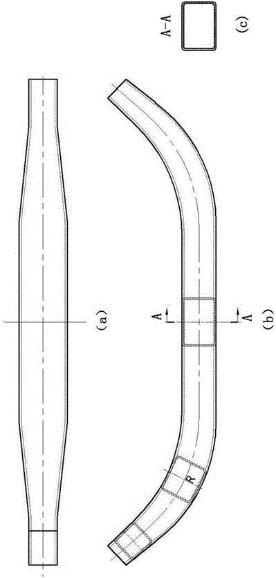
[0051] A heat-shrink forming method for a C-beam of a variable section rectangular tube, which includes the following steps:

[0052] (1) Equal reduction in diameter: The two ends of the seamless round pipe are heated to 900-980℃ in an intermediate frequency furnace. Preferably, the seamless round pipe is a seamless steel pipe with a thickness of 6-7mm, which is used on the extrusion equipment The necking mold performs equal diameter reduction, and the two ends of the round tube are made into a conical tube, and the small end of the conical tube is outside, and the conical tubes at both ends have an equal cone angle, and the cone angle of the conical tube after equal reduction in diameter It is 1.5゜-4゜, preferably the cone angle of the conical tube after the same reduction is 2.2゜, a...


PUM

PropertyMeasurementUnit
thicknessaaaaaaaaaa

Abstract

The invention provides a thermal shrinkage molding method of a C-shaped beam of a variable cross-section rectangular pipe. The method comprises the following working procedures: (1) carrying out equivalent drawing-down, namely, heating the two ends of a seamless round tube by an intermediate frequency furnace, and then making the two ends of the round tube into conical tubes, wherein the small end is arranged outside; (2) carrying out variable drawing-down, namely, heating the conical tubes at the two ends of the round tube by the intermediate frequency furnace based on the working procedure (1), and making the conical tube at each end into two sections of continuous conical tubes with different taper angles; (3) processing the middle part by square pushing, namely, enabling the circular tube in the middle part to be rolled into a square tube in a forced way by a square pushing machine; (4) pressing the two ends to be square, namely, pressing the two sections of conical tubes with different taper angles at the two ends into two sections of tubes which have different taper angles and rectangular cross sections; and (5) carrying out whole bend molding, namely, pressing the whole tube into a C-shaped beam body. The molding method is fewer in working procedures, high in production efficiency and high in product quality stability.

Description

Technical field [0001] The invention relates to a processing and forming method of a variable section beam, in particular to a heat shrinkage forming method of a variable section rectangular tube C-shaped beam. Background technique [0002] With the development of society and economy and the progress of science, people's living standards have been continuously improved. Traveling is the main choice for most people to improve their quality of life. However, because most tourist attractions are mostly in mountainous areas or mountain villages, trains, high-speed trains, and high-speed railways are often not directly accessible. Self-driving travel costs are high, routes are unfamiliar, and tickets are high, which makes travel very inconvenient. Therefore, group travel by passenger car is the best choice. [0003] At present, with the improvement of the level of science and technology, the technical equipment capabilities of passenger cars continue to improve to meet the increasing ne...

Claims


Application Information

Patent Timeline
Patent Type & Authority Patents(China)
IPC IPC(8): B21C37/15
CPCB21C37/15
Inventor 高建路肖桂荣丁海峰肖红凌
Owner 南通壹选智能科技有限公司
Why Eureka
Try Eureka