
Sensor and lithographic apparatus

A sensor and radiation sensor technology, applied in microlithography exposure equipment, optomechanical equipment, instruments, etc., can solve the problems of unsuitable radiation sensor, sensor damage, etc.

Active Publication Date: 2015-07-22
ASML NETHERLANDS BV
View PDF9 Cites 4 Cited by
  • Summary
  • Abstract
  • Description
  • Claims
  • Application Information

AI Technical Summary

Problems solved by technology

While such high-temperature boron deposition techniques may be suitable for the fabrication of imaging sensors of simple construction, such as transmission imaging sensors, it has been found to be unsuitable for the fabrication of CMOS or CCD-based radiation sensors due to factors such as internal circuitry, wiring, or polysilicon gates. Parts of the sensor such as poles are damaged

Method used


Image

  • Sensor and lithographic apparatus
  • Sensor and lithographic apparatus
  • Sensor and lithographic apparatus

Examples


Embodiment Construction

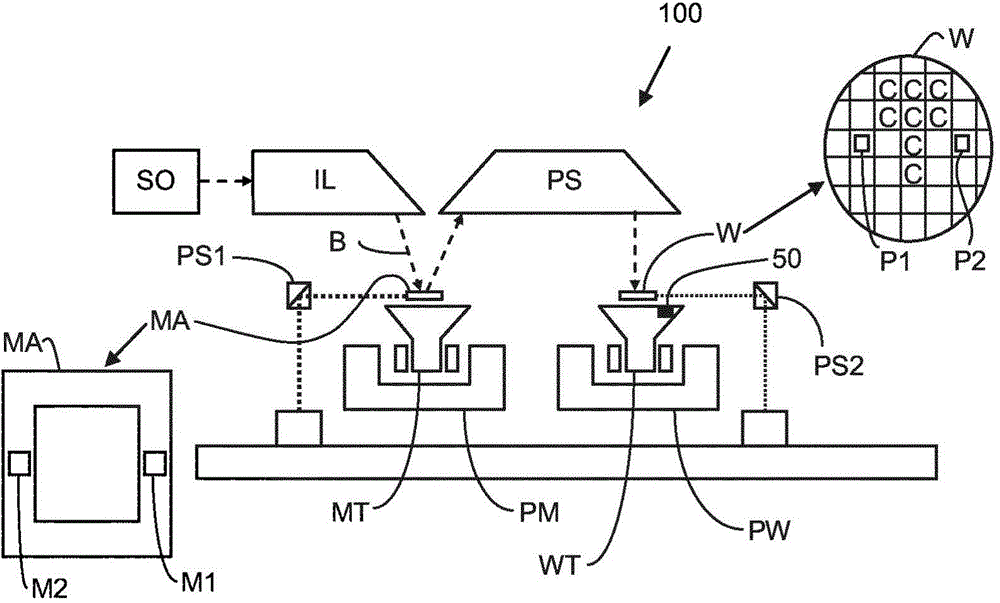
[0052] This specification discloses embodiments that incorporate the features of this invention. The disclosed embodiments merely illustrate the invention. The scope of the invention is not limited to the disclosed embodiments. The present invention is defined by the claims and clauses appended hereto.

[0053] Embodiments are described, and references in the specification to "one embodiment," "an embodiment," "example embodiments," "some embodiments," etc. indicate that the described embodiments may include a particular feature, structure, or characteristic, However, each embodiment may not necessarily include a specific feature, structure or characteristic. Moreover, such phrases are not necessarily referring to the same embodiment. Further, when a specific feature, structure or characteristic is described in conjunction with an embodiment, it is understood that it is within the knowledge of those skilled in the art to realize such feature, structure or characteristic in ...


PUM

PropertyMeasurementUnit
Thicknessaaaaaaaaaa

Abstract

A backside illuminated sensor comprising a supporting substrate, a semiconductor layer which comprises a photodiode comprising a region of n-doped semiconductor provided at a first surface of the semiconductor layer, and a region of p-doped semiconductor, wherein a depletion region is formed between the region of n-doped semiconductor and the region of p-doped semiconductor, and a layer of p-doping protective material provided on a second surface of the semiconductor layer, wherein the first surface of the semiconductor layer is fixed to a surface of the supporting substrate.

Description

[0001] Cross References to Related Applications [0002] This application claims the benefit of US Provisional Application 61 / 720,700, filed October 31, 2012, which is hereby incorporated by reference in its entirety. technical field [0003] The invention relates to sensors and lithographic apparatus. Background technique [0004] A lithographic apparatus is a machine that applies a desired pattern onto a substrate, usually onto a target portion of the substrate. For example, lithographic equipment may be used in the manufacture of integrated circuits (ICs). In this case, a patterning device (alternatively referred to as a mask or reticle) may be used to create the circuit pattern to be formed on the individual layers of the IC. The pattern may be transferred onto a target portion (eg, comprising a portion of a die, one or several dies) on a substrate (eg, a silicon wafer). The transfer of the pattern is usually via imaging onto a layer of radiation sensitive material (...

Claims


Application Information

Patent Timeline
IPC IPC(8): G03F7/20H01L27/146H01L27/148
CPCH01L27/14643H01L27/14689G03F7/70558G03F7/7085H01L27/1464H01L27/14609H01L31/028H01L31/035281H01L31/1804
Inventor S·尼蒂亚诺维H·科克M·威伦斯
Owner ASML NETHERLANDS BV
Learn More