Bidirectional waste heat recovery device for outdoor air pretreatment of air conditioner

A waste heat recovery device and pretreatment technology, applied in the field of air conditioning engineering, can solve the problems of complex system, power consumption, air quality decline, etc., and achieve the effects of high energy recovery rate, avoiding fresh air pollution, and reducing structure size

Active Publication Date: 2015-08-05
SUZHOU QIAN COLORS TEXTILE CHEM FIBER
View PDF8 Cites 7 Cited by
  • Summary
  • Abstract
  • Description
  • Claims
  • Application Information

AI Technical Summary

Problems solved by technology

The patent application number is 200820049766.9 discloses a wheel heat recovery type energy recovery device, its principle is to use the heat storage and water absorption of the rotor core to recover the cold or heat in the exhaust air, and the recovered Cooling or heat is directly transferred to the fresh air, and the heat exchange efficiency of the rotor-type energy recovery device is high, but it requires cross-exchange heat exchange between fresh air and exhaust air, and exhaust gas pollutes fresh air, causing air quality degradation, which does not meet public health requirements, and Not suitable for maintenance and cleaning
[0005] The patent with the application number 201120456593.4 discloses a heat pump heat recovery type energy recovery device. Its principle is to place the condenser and evaporator of the heat pump unit in the exhaust air duct and the fresh air duct respectively, and change the cooling / cooling capacity of the unit according to the seasonal working conditions. The thermal cycle mode realizes the cross-change of the functions of the condenser and the evaporator, recovers the cold and heat energy of the exhaust air and applies it to the fresh air for cooling, dehumidification or heating. The wind cross-contaminates each other, but it needs to consume power, and the system is complex and expensive
[0006] The patent with the application number 200710062644.3 discloses an energy recovery device using a thermosiphon. The fresh air and the fresh air flow through the two boxes respectively, and the energy exchange between the two airflows is realized through the heat exchange cores in them. The operating conditions and capacities are changed under the drive of the ejector rod and the driving device outside the box. The energy recovery device converts the heat The siphon tube, a new type of high-efficiency heat exchange element, is used in energy recovery, and its structure is relatively simple, but it needs to collect all the exhaust air in the air conditioning system, and then pre-treat the fresh air, which makes the structure of the device huge and cannot be widely used In the field of limited space structure, at the same time, the structure of the heat exchange efficiency adjustment mechanism is complex, the top frame and the outer frame are fixedly connected, the actual application process is difficult to operate, and a power device is required to drive
[0007] The use of full heat exchange energy recovery devices is more common, and its notable feature is the integrated structure, which is easy to apply, stable and reliable, but the efficiency is low, and there is also the danger of pollutants or viruses in the exhaust air penetrating into the fresh air

Method used


Image

  • Bidirectional waste heat recovery device for outdoor air pretreatment of air conditioner
  • Bidirectional waste heat recovery device for outdoor air pretreatment of air conditioner
  • Bidirectional waste heat recovery device for outdoor air pretreatment of air conditioner

Examples


Embodiment Construction

[0024] In order to make the objectives and technical solutions of the embodiments of the present invention clearer, the technical solutions of the embodiments of the present invention will be further described clearly and completely in conjunction with the accompanying drawings of the embodiments of the present invention.

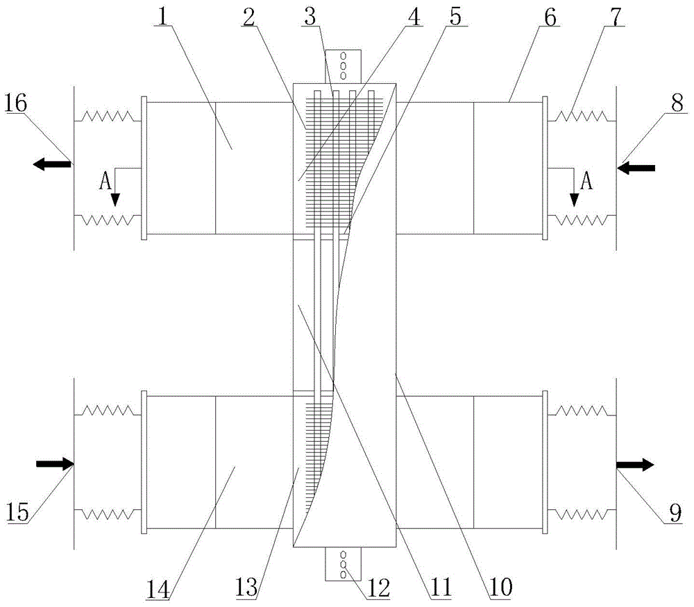
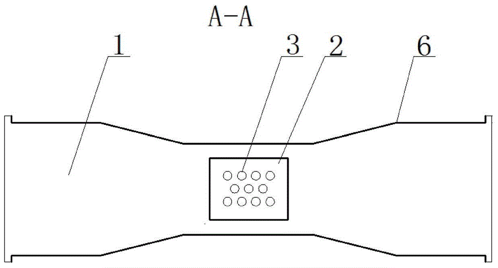
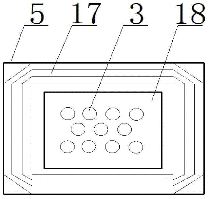
[0025] As attached Figure 1 to 4 Shown here is a two-way waste heat recovery device for air conditioning fresh air pretreatment of the present invention, on the walls of the corresponding air duct shell 6 of the exhaust air heat exchange duct 1 and the fresh air heat exchange duct 14 arranged in parallel and isolated A through hole with a coaxial line is opened, and an open sealing partition 5 is installed in the through hole, and a universal telescopic structure 17 and an internal fixed partition 18 are sequentially installed in the hole of the sealing partition 5 from the outside to the inside. A total of 11 heat pipes 3 arranged in an inverted and authenti...


PUM


Abstract

Disclosed is a bidirectional waste heat recovery device for outdoor air pretreatment of an air conditioner. The corresponding duct housing walls of an exhaust heat exchange duct and an outdoor air heat exchange duct are provided coaxial through holes; a sealing separating plate with a hole is mounted inside the through holes, and the inside of the hole of the sealing separating plate is sequentially provided with a universal retractable structure and an internal fixed separating plate from outside to inside; a plurality of heat pipes are arranged arrays in the internal fixing plate in a penetrating mode through holes formed in the internal fixing plate; the heat pipes penetrating the exhaust heat exchange duct and the outdoor air heat exchange duct are provided with a plurality of fins in a sleeving mode; a thermal insulating cavity is arranged outside the heat pipes between the exhaust heat exchange duct and the outdoor air heat exchange duct; both ends of the housing of the exhaust heat exchange duct and the outdoor air heat exchange duct are connected with retracting structures; the duct housing walls at both ends of the heat pipes are symmetrically provided with a variable resetting mechanism for lifting the ducts up and down. The bidirectional waste heat recovery device for outdoor air pretreatment of the air conditioner is simple in structure, convenient to operate, free in adjustment of operational conditions and heat exchange efficiency and high in energy recovery rate.

Description

Technical field [0001] The invention relates to an air conditioner exhaust air energy recovery device, in particular to an energy recovery device that recovers the waste heat of indoor exhaust air to preheat or precool fresh air of the air conditioner, and belongs to the technical field of air conditioning engineering. Background technique [0002] In today's increasingly severe energy situation, energy conservation and environmental protection have become a basic national policy of our country. Central air-conditioning systems have been widely used in all walks of life, and have become one of the infrastructures of various land buildings and ships. Platoon has received more and more attention and attention. Statistics show that the total energy consumption of buildings in China is increasing year by year, and the proportion of total energy consumption has risen from 10% in the late 1970s to 27.8% in recent years. The biggest energy consumption of buildings is heating and air co...

Claims


Application Information

Patent Timeline
Patent Type & Authority Applications(China)
IPC IPC(8): F24F12/00
CPCF24F12/002F24F2012/005
Inventor 赵忠超云龙杜军张霄史策周根明
Owner SUZHOU QIAN COLORS TEXTILE CHEM FIBER
Why Eureka
Try Eureka