
A condensing gas flue gas waste heat recovery device

A flue gas waste heat recovery device technology, applied in air heaters, fluid heaters, climate change adaptation and other directions, can solve problems such as heat loss, low boiler efficiency, waste of resources, etc. The effect of improving and recycling efficiency

Inactive Publication Date: 2017-12-26
BAODING HENGYU MECHANICAL & ELECTRICAL MFG
View PDF6 Cites 0 Cited by
  • Summary
  • Abstract
  • Description
  • Claims
  • Application Information

AI Technical Summary

Problems solved by technology

[0002] The exhaust gas temperature of gas-fired boilers is generally 120-250°C. The flue gas contains 8%-15% sensible heat and 11% latent heat of water vapor. If it cannot be recycled, it will lead to low efficiency of the boiler and a large resource waste. waste, while the flue gas contains CO 2 , NOx, SO 2 Hazardous substances such as smoke and dust, if discharged into the atmosphere, will have a bad impact on the environment
[0003] Before the present invention was made, heat pump technology was used to solve this kind of problem, but the use of heat pump requires expensive equipment investment, consumes a lot of electric energy, and the amount of flue gas treatment is limited, so it is difficult to popularize and apply
The flue gas condenser is a mature equipment for reducing the exhaust gas temperature. The current flue gas condenser is not very effective in exchanging heat with low-temperature flue gas with low thermal quality, and is restricted by the flue gas dew point corrosion. When the exhaust gas temperature drops above the flue gas dew point temperature (about 57°C), there is still a large amount of heat loss, and the problem of pollutant emission cannot be effectively solved.

Method used


Image

  • A condensing gas flue gas waste heat recovery device
  • A condensing gas flue gas waste heat recovery device
  • A condensing gas flue gas waste heat recovery device

Examples


Embodiment Construction

[0031] The present invention will be further described below in conjunction with accompanying drawing:

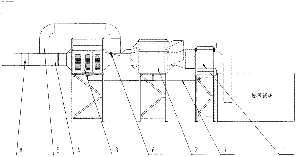
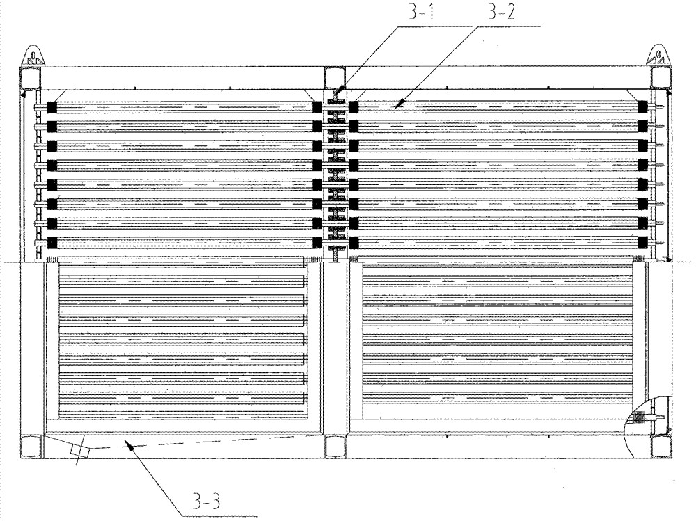
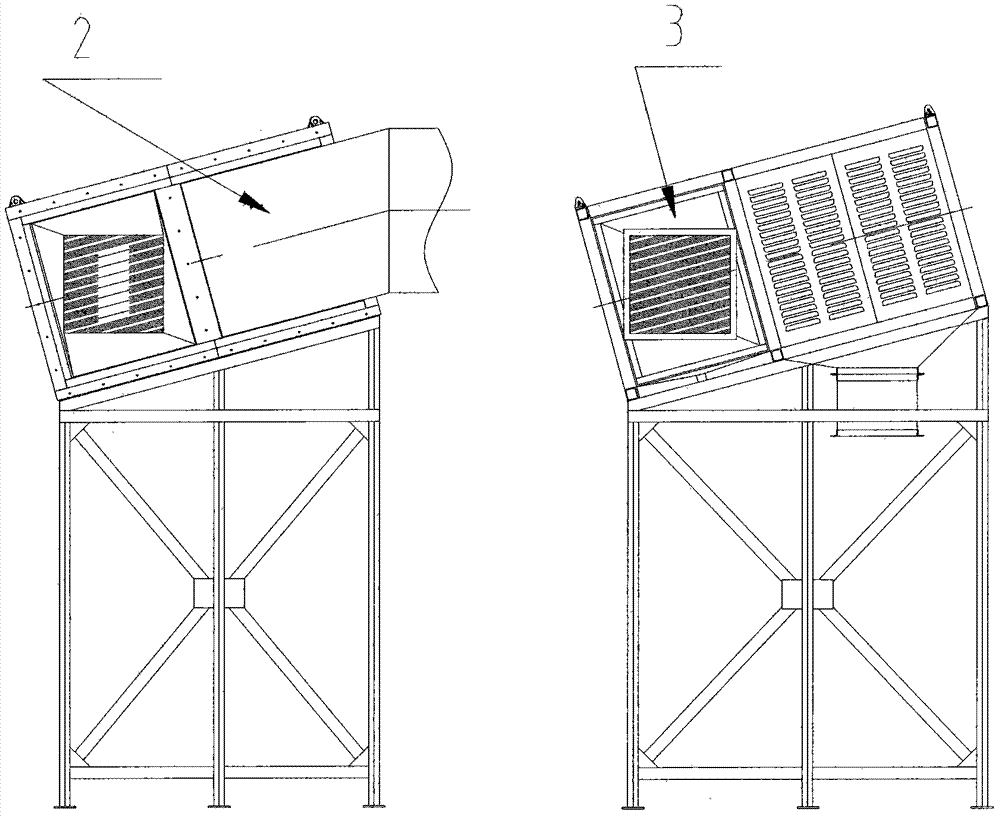
[0032] A new type of condensing gas flue gas waste heat recovery device with energy saving and environmental protection functions, such as figure 1 As shown, a three-stage integrated structure of A, B, and C is adopted, and the heat exchange is condensed and heat-exchanged in stages. Condensing gas flue gas waste heat recovery device Class A 1 is a shell-and-tube gas-water heat exchanger, which is used to heat the return water of the boiler pipe network and reduce the flue gas temperature to 100-120 ° C; condensing gas flue gas waste heat recovery device Class B 2 is a heat pipe type gas-gas heat exchanger, which is used to heat the boiler blast, raise the outdoor cold air to 35°C, and reduce the flue gas temperature to 60-80°C; Condensing gas flue gas waste heat recovery device C Class 3 The low-temperature heat transfer element 3-2 with excellent low-temperature heat tra...


PUM


Abstract

The invention relates to a condensed gas waste heat recovery device which is an energy-saving environment-friendly product related to a gas boiler. The condensed gas waste heat recovery device adopts an A, B and C three-level integrated structure, condensation and heat exchange are perfumed level by level, the A level is used for heating supplied water of the boiler, the B level is used for heating blowing air of the boiler, and the C level adopts a low temperature heat transfer element and is subject to forcible convection and heat exchange with outdoor cold air, exhaust smoke temperature of the boiler is reduced to 32 DEG C, most vapor in the smoke becomes condensed water, and harmful substances such as CO2, NOx, SO2 and dust in the smoke are dissolved in the condensed water which is timely drained by a drainage system, thus greatly reducing the emission of pollutants, solving the problem of white smoke of the boiler in the prior art, achieving obvious energy-saving consumption reduction, emission reduction and atmosphere protection, and effectively weakening the urban heat island effect.

Description

technical field [0001] The invention relates to a condensing gas flue gas waste heat recovery device, which is an energy-saving and environmentally friendly product related to boilers, and is suitable for reducing the exhaust gas temperature of gas boilers, recovering flue gas waste heat, improving boiler efficiency, and reducing CO in flue gas. 2 , NOx, SO 2 , smoke and dust and other harmful substances to the atmosphere, and eliminate the gas flue gas condensation equipment that emits white smoke from the boiler. Background technique [0002] The exhaust gas temperature of gas-fired boilers is generally 120-250°C. The flue gas contains 8%-15% sensible heat and 11% latent heat of water vapor. If it cannot be recycled, it will lead to low efficiency of the boiler and a large resource waste. waste, while the flue gas contains CO 2 , NOx, SO 2 Hazardous substances such as smoke and dust, if discharged into the atmosphere, will have a bad impact on the environment. [0003]...

Claims


Application Information

Patent Timeline
Patent Type & Authority Patents(China)
IPC IPC(8): F24H8/00F24H9/16
CPCY02A30/60Y02B30/00
Inventor 孔凡涛张建鹏王绍君金成李东来崔大利
Owner BAODING HENGYU MECHANICAL & ELECTRICAL MFG
Learn More