Simulation platform for simulating high and low frequency motion of vehicle and implementation method thereof
A simulation platform and vehicle technology, applied in educational appliances, teaching models, instruments, etc., can solve the problems of inability to simulate the motion of large-scale carrier equipment, small load/driver power ratio, and increase system cost, so as to improve work accuracy and visualization. Monitoring, increasing the ratio of power, and realizing the effect of real-time detection
- Summary
- Abstract
- Description
- Claims
- Application Information
AI Technical Summary
Problems solved by technology
Method used
Image
Examples
Embodiment 1
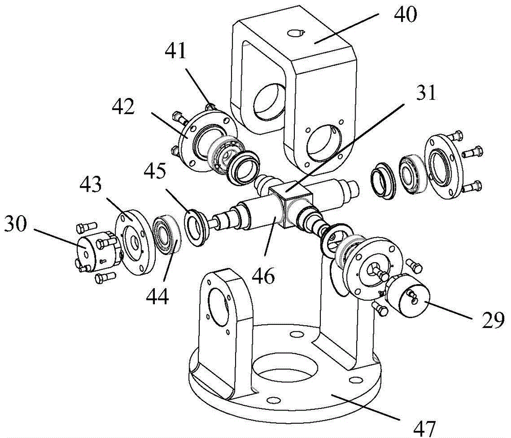
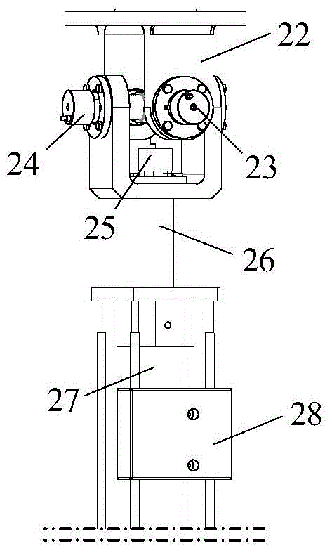
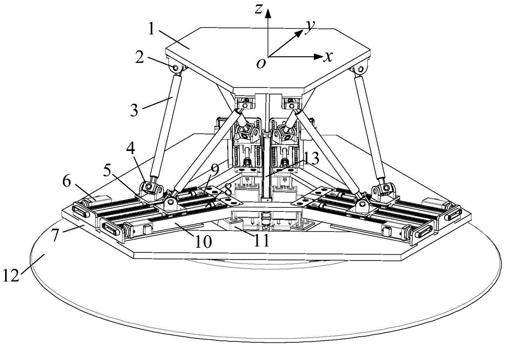
[0020] A simulation platform for simulating the high and low frequency movement of vehicles, the parallel dual-drive simulation platform includes an output platform, an attitude adjustment platform and a detection branch, and its structural diagram is as follows figure 1 As shown; the output platform includes a moving platform 1, a ball joint 2, a linear motion actuator 3 and a universal joint 4; the attitude adjustment platform includes a guide rail seat 10, a fixed platform 7, a slider 5, a servo motor 6, a linear Guide rail 9, ball screw 8, base 12 and static load balancing device 11, the static load balancing device 11 includes steel wire rope 14, fixed pulley A15, pressure plate 16, double column 17, fixed pulley B18, suspension ring 19, counterweight 20, Column seat 21; the shape of the moving platform 1 is hexagonal, and mounting holes are evenly distributed on its edge; there are six spherical hinges 2, two adjacent ones are set as a group, and the upper hinge seat of t...
Embodiment 2
[0022] A simulation platform for simulating the high and low frequency movement of vehicles, the parallel dual-drive simulation platform includes an output platform, an attitude adjustment platform and a detection branch, and its structural diagram is as follows figure 1 As shown; the output platform includes a moving platform 1, a ball joint 2, a linear motion actuator 3 and a universal joint 4; the attitude adjustment platform includes a guide rail seat 10, a fixed platform 7, a slider 5, a servo motor 6, a linear Guide rail 9, ball screw 8, base 12 and static load balancing device 11, the static load balancing device 11 includes steel wire rope 14, fixed pulley A15, pressure plate 16, double column 17, fixed pulley B18, suspension ring 19, counterweight 20, Column seat 21; the shape of the moving platform 1 is rectangular, and mounting holes are evenly distributed on its edge; there are six spherical hinges 2, and two adjacent ones are set as a group, and the upper hinge sea...
Embodiment 3
[0024] For the implementation method of the emulation platform described in embodiment 1 or 2, its flow process is as Figure 8 As shown, the specific steps are as follows: a) Obtain vehicle motion data, and use linear interpolation method to establish the change curve of the six-dimensional pose and running time of the moving platform 1; set the system parameters, and select the linear motion actuator 3 with a moving range of -20 ~20mm, servo cycle is 4ms, motion curve interval is 250 frames / second; servo motor 6 moving range is -700~700mm, servo cycle is 10ms, motion curve interval is 100 frames / second; running time corresponds to vehicle motion data The time is consistent; b) decompose the motion with a frequency above 5Hz to the output platform; decompose the motion with a frequency below 5Hz to the attitude adjustment platform; c) use the kinematics model of the parallel mechanism to map the motion of the output platform and the attitude adjustment platform to its straight...
PUM
| Property | Measurement | Unit |
|---|---|---|
| Circumcircle diameter | aaaaa | aaaaa |
Abstract
Description
Claims
Application Information
 - R&D
- Intellectual Property
- Life Sciences
- Materials
- Tech Scout
- Unparalleled Data Quality
- Higher Quality Content
- 60% Fewer Hallucinations
Browse by: Latest US Patents, China's latest patents, Technical Efficacy Thesaurus, Application Domain, Technology Topic, Popular Technical Reports.
© 2025 PatSnap. All rights reserved.Legal|Privacy policy|Modern Slavery Act Transparency Statement|Sitemap|About US| Contact US: help@patsnap.com


