Shallow trench isolation structure preparation method

A shallow trench isolation and trench technology, applied in semiconductor/solid-state device manufacturing, electrical components, circuits, etc., can solve problems such as leakage current increase, isolation failure, uneven surface shape, etc., to improve device reliability, Reduce device leakage current, avoid oxidation and corrosion effects

Active Publication Date: 2015-08-12
SEMICON MFG INT (SHANGHAI) CORP
View PDF7 Cites 7 Cited by
  • Summary
  • Abstract
  • Description
  • Claims
  • Application Information

AI Technical Summary

Problems solved by technology

However, the LOCOS process has a series of disadvantages: 1) There is a phenomenon of "bird's beak" (bird's beak) growing on the edge of silicon nitride, and the "bird's beak" takes up the actual space and increases the volume of the circuit. The "mouth" makes the field silicon oxide invade the active area; 2) The field implantation redistributes during the high temperature oxidation process, causing the narrow width effect of the active device (narrow width effect); 3) The field silicon oxide becomes thinner in the narrow isolation area; 4) Uneven surface shape
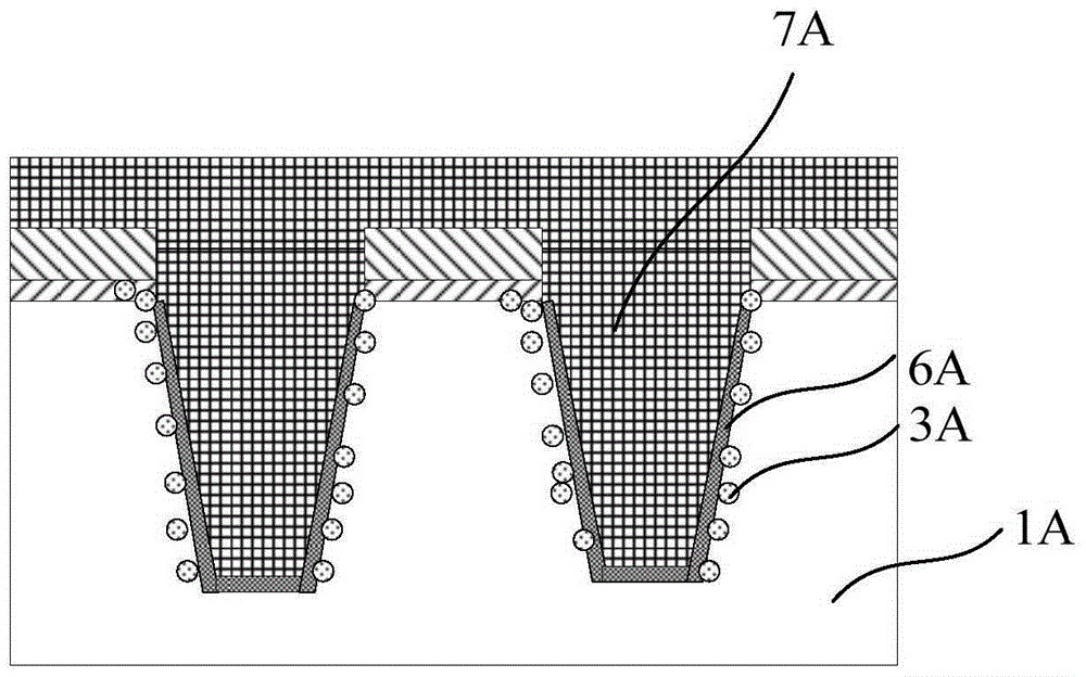
[0008] In the prior art, high-density plasma chemical vapor deposition is used for the formal filling of insulating materials, and the semiconductor substrate 1A is preheated and initially deposited. Both preheating and initial deposition occur in the reaction chamber process, and the reaction process chamber has O 2 The plasma environment formed with He gas, due to the preheating and initial deposition stage, the trench surface is exposed to the plasma environment, O plasma will oxidize or chemically attack the trench wall, and form defects 3A on the trench surface, such as figure 1 As shown, this will lead to increased leakage current and even isolation failure
In addition, in the existing process, a lining oxide layer 6A is generally prepared on the trench surface as a buffer layer before filling the insulating material 7A. However, since the lining oxide layer 6A is prepared by thermal oxidation, its thickness is only about 100 angstroms, and it is not Therefore, even if there is a liner oxide layer 6A on the surface of the trench, it cannot resist the oxidation and erosion of the plasma on the surface of the trench

Method used


Image

  • Shallow trench isolation structure preparation method
  • Shallow trench isolation structure preparation method
  • Shallow trench isolation structure preparation method

Examples


Embodiment Construction

[0032] Embodiments of the present invention are described below through specific examples, and those skilled in the art can easily understand other advantages and effects of the present invention from the content disclosed in this specification. The present invention can also be implemented or applied through other different specific implementation modes, and various modifications or changes can be made to the details in this specification based on different viewpoints and applications without departing from the spirit of the present invention.

[0033] Please refer to attached picture. It should be noted that the diagrams provided in this embodiment are only schematically illustrating the basic idea of ​​the present invention, and only the components related to the present invention are shown in the diagrams rather than the number, shape and shape of the components in actual implementation. Dimensional drawing, the type, quantity and proportion of each component can be change...


PUM


Abstract

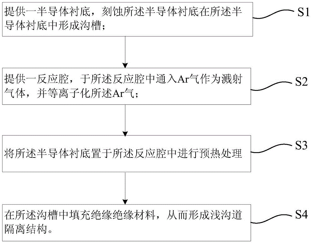
The invention provides a shallow trench isolation (STI) structure preparation method, at least comprising the steps of: providing a semiconductor substrate, and etching the semiconductor substrate to form trenches in the semiconductor substrate; providing a reaction chamber, into which Ar gas is inputted as sputtering gas, and ionizing the Ar gas; placing the semiconductor substrate in the reaction chamber to perform preheating treatment; and filling insulating materials in the trenches so as to form an STI structure. According to the invention, in a semiconductor substrate preheating phase, Ar gas is employed as plasma source gas to replace O2 of the traditional process, thereby preventing the surfaces of the trenches of the semiconductor substrate in the preheating phase from being oxidized and corroded by O plasmas, reducing device leak current, preventing a device from isolation failure, and improving device reliability. In addition, Ar plasmas can improve the dissociation effect of a whole plasma system, which is in favor of performing the filling process smoothly.

Description

technical field [0001] The invention relates to the field of semiconductor technology, in particular to a preparation method of a shallow trench isolation structure. Background technique [0002] With the development of semiconductor technology, the feature size of devices in integrated circuits has become smaller and smaller, and the speed of devices and systems has increased accordingly. After the semiconductor process enters the deep submicron stage, in order to realize high-density, high-performance devices and circuits, the isolation and planarization process becomes more and more important. [0003] At present, methods for forming isolation regions mainly include local oxidation isolation process (LOCOS) or shallow trench isolation process (STI). [0004] The LOCOS process is to deposit a layer of silicon oxide on the surface of the wafer, and then perform etching to oxidize and grow silicon oxide in part of the recessed area, and the active device is generated in the...

Claims


Application Information

Patent Timeline
Patent Type & Authority Applications(China)
IPC IPC(8): H01L21/762
Inventor 张玉宁振佳单伟中何海杰袁嘉国
Owner SEMICON MFG INT (SHANGHAI) CORP
Why Eureka
Try Eureka