Automatic balance adjusting system of mechanical arms

A technology of automatic balancing and adjustment system, applied in the direction of fluid pressure actuation system components, mechanically driven excavators/dredgers, mechanical equipment, etc. structure, the effect of reducing energy consumption

Inactive Publication Date: 2015-08-19
QIQIHAR UNIVERSITY
View PDF5 Cites 5 Cited by
  • Summary
  • Abstract
  • Description
  • Claims
  • Application Information

AI Technical Summary

Problems solved by technology

[0004] The purpose of the present invention is to provide an automatic balance adjustment system of a mechanical arm to solve the problem that the existing mechanical arm will do useless work when moving due to its own weight, and at the same time this useless work will consume a large amount of mechanical power

Method used


Image

  • Automatic balance adjusting system of mechanical arms
  • Automatic balance adjusting system of mechanical arms
  • Automatic balance adjusting system of mechanical arms

Examples


specific Embodiment approach 1

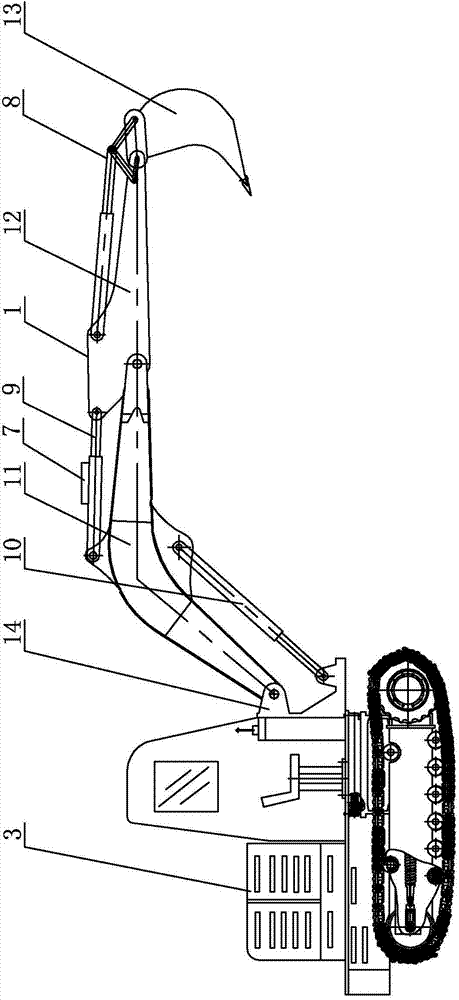
[0022] Specific implementation mode one: combine figure 1 , figure 2 , image 3 , Figure 4 with Figure 5 Describe this embodiment, in this embodiment it includes at least one mechanical arm 1, at least one hydraulic cylinder assembly 2, hydraulic drive system 3, intelligent control system and a plurality of accumulators 7, the signal output terminal of the intelligent control system sends out the control signal For the hydraulic drive system 3, the hydraulic drive system 3 controls the movement of at least one hydraulic cylinder 2, and each mechanical arm 1 is equipped with a hydraulic cylinder assembly 2, the movement of the hydraulic cylinder assembly 2 drives the movement of the mechanical arm 1, and at least one hydraulic cylinder assembly 2 A plurality of energy accumulators 7 are installed above the upper part, and the energy accumulators 7 are used to store the gravitational potential energy generated when the mechanical arm 1 falls, and provide energy for the mec...

specific Embodiment approach 2

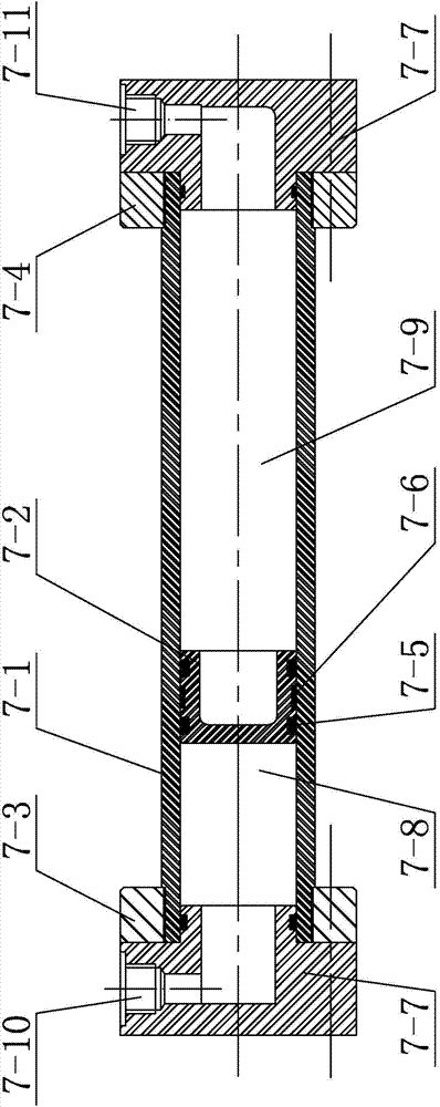
[0026] Specific implementation mode two: combination figure 2 with image 3 This embodiment will be described. In this embodiment, one hydraulic cylinder assembly 2 is correspondingly provided with two accumulators 7 . Through the sample test, it can be concluded that one hydraulic cylinder assembly 2 is equipped with two accumulators 7 so that the energy storage effect of the accumulator 7 on its corresponding hydraulic cylinder assembly 2 is the best. Such setting is scientific and reasonable. Other unmentioned components and connections are the same as those in the first embodiment.

specific Embodiment approach 3

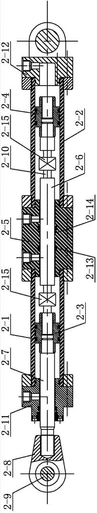
[0027] Specific implementation mode three: combination figure 1 , figure 2 , image 3 , Figure 4 with Figure 5Describe this embodiment. In this embodiment, the hydraulic cylinder assembly 2 includes a first component cylinder 2-1, a second component cylinder 2-2, a first piston 2-3, a second piston 2-4, and an inter-cylinder coupling body 2- 5. Transition piston rod 2-6, first piston rod 2-7, second piston rod 2-10, coupling ring 2-8, first pin shaft 2-9, first end cover 2-11, second end Cover 2-12, two universal joints 2-15, an inter-cylinder coupling body 2-5 is fixedly connected between the first component cylinder 2-1 and the second component cylinder 2-2, the first The first piston rod 2-7 is pierced inside the component cylinder 2-1, and the end of the first component cylinder 2-1 away from the connecting body 2-5 between cylinders is provided with a first end cover 2-11, and the first piston rod 2- 7. There is a first piston 2-3 on the upper sleeve, and one end ...


PUM


Abstract

The invention provides an automatic balance adjusting system of mechanical arms, and relates to an automatic balance adjusting system. By the automatic balance adjusting system of the mechanical arms, the problems that the existing mechanical arm can apply idle work during movement due to the gravity of the existing mechanical arm, and the idle work can consume a large amount of mechanical power are solved. The automatic balance adjusting system comprises at least one mechanical arm, at least one hydraulic cylinder subassembly, a hydraulic driving system, an intelligent control system and a plurality of energy accumulators; a signal outputting end of the intelligent control system transmits a control signal to the hydraulic driving system; the hydraulic driving system controls movement of at least one hydraulic cylinder; each mechanical arm is matched with the corresponding hydraulic cylinder subassembly; each hydraulic cylinder subassembly moves to drive the corresponding mechanical arm to move; and the energy accumulators are arranged on the hydraulic cylinder subassemblies. Gravitational potential energy of the mechanical arms which work in a reciprocating manner is stored in the energy accumulators, and is released when the mechanical arms rise, power consumption on rising of the mechanical arms is reduced effectively, and the mechanical arms are prevented from applying idle work to a maximum extent. By the automatic balance adjusting system, ascending and descending of the mechanical arms can be adjusted.

Description

technical field [0001] The invention specifically relates to an automatic balance adjustment system of a mechanical arm. Background technique [0002] The robotic arm is currently the most widely used automated mechanical device in the field of robotics. It can be seen in industrial manufacturing, medical treatment, entertainment services, military, semiconductor manufacturing, and space exploration. Although their shapes are different, they all have a common feature, that is, they can accept instructions and precisely locate a certain point in two-dimensional or three-dimensional space for operation. [0003] For example, in construction machinery, the mechanical arm on the excavator or the cantilever crane needs to overcome the influence of gravity during the working process. Its self-weight during the lifting process often consumes a lot of mechanical power to do useless work, and these powers account for almost 10% of the total energy consumption. 50%, this situation no...

Claims


Application Information

Patent Timeline
Patent Type & Authority Applications(China)
IPC IPC(8): E02F3/42B66C23/683F15B1/02F15B1/08F15B21/02
Inventor 米粮川
Owner QIQIHAR UNIVERSITY
Why Eureka
Try Eureka