
Random scattering optical imaging system and random scattering optical imaging method based on sparse representation

An optical imaging system, sparse representation technology, applied in optics, optical components, components of TV systems, etc., can solve the problems of huge amount of reconstruction data, poor real-time imaging, and long time consumption, to simplify the structure and reduce imaging. cost, the effect of reducing computational complexity

Inactive Publication Date: 2015-08-19
XIDIAN UNIV
View PDF4 Cites 31 Cited by
  • Summary
  • Abstract
  • Description
  • Claims
  • Application Information

AI Technical Summary

Problems solved by technology

The wavefront modulation technology adjusts the wavefront of the incident light wave through feedback control, so that the adjusted light wave can be focused after passing through a random scattering medium. However, this imaging system based on optical phase conjugation has a complex optical path, poor real-time imaging and anti-noise performance. Poor, not suitable for imaging in noisy environments
The speckle field reconstruction technology realizes imaging by extracting the initial incident light wave information from the received speckle field image. It has good anti-noise performance, but it needs to measure the transmission matrix of the random scattering medium and directly reconstruct the entire speckle field. Huge, takes a long time

Method used


Image

  • Random scattering optical imaging system and random scattering optical imaging method based on sparse representation
  • Random scattering optical imaging system and random scattering optical imaging method based on sparse representation
  • Random scattering optical imaging system and random scattering optical imaging method based on sparse representation

Examples


Embodiment Construction

[0035] The setting of the random scattering optical imaging system based on sparse representation of the present invention will be clearly and completely described below in conjunction with the accompanying drawings, and an image reconstruction algorithm based on compressed sensing theory is used to process the coded speckle field image received by the detector array, and calculate The target image is recovered, and the background noise in the imaging process is removed at the same time.

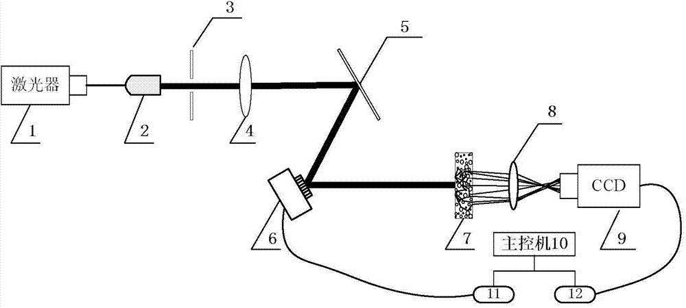
[0036] refer to figure 1 , the imaging system of the present invention includes a light source 1, a spatial filter 2, an aperture stop 3, a collimator lens 4, a mirror 5, a spatial light modulator 6, a random scattering medium 7, a lens 8, a detector array 9 and a main control Machine 10. Among them: the light source 1 adopts a laser light source in the visible light band; the random scattering medium 7 adopts frosted glass with both strong scattering characteristics and good transmission c...


PUM


Abstract

The invention discloses a random scattering optical imaging system and a random scattering optical imaging method based on sparse representation. The imaging system comprises a light source (1), a spatial filter (2), an aperture diaphragm (3), a collimating lens (4), a reflector (5), a spatial light modulator (6), a random scattering medium (7), a lens (8), a detector array (9), and a main control computer (10). Light emitted by the light source enters the spatial light modulator via the reflector after passing through the spatial filter, the aperture diaphragm and the collimating lens. The main control computer loads an imaging target on the spatial light modulator, so that light emitted from the spatial light modulator and carrying target information forms a coding speckle field image on the detector array after passing through the random scattering medium and the lens, and the coding speckle field image is transmitted to the main control computer. The main control computer decodes and reconstructs the coding speckle field image and removes background noise to obtain a target image. The random scattering optical imaging system of the invention has a simple structure, good real-time performance and high noise resistance. The system and the method of the invention can be used for random scattering high-speed imaging in a noise environment in the laboratory.

Description

technical field [0001] The invention belongs to the technical field of image processing and imaging, relates to an optical imaging system and image reconstruction, and can be used for high-speed random scattering imaging in a noisy environment in a laboratory. Background technique [0002] In random scattering media such as biological tissues and clouds, there is often multiple scattering, and the mean free path of light propagation inside the medium is extremely short, resulting in the loss of the relative position of the original incident light field when the light incident on the random scattering medium exits. relationship and cannot be clearly imaged. For example, satellite remote sensing imaging needs to collect light reflected from ground targets and pass through the atmosphere. For example, in the case of non-invasive and non-destructive detection, it is necessary to perform in-depth imaging of biological tissues, but due to the scattering of particles inside biolog...

Claims


Application Information

Patent Timeline
Patent Type & Authority Applications(China)
IPC IPC(8): G02B27/58H04N5/232
CPCG02B27/58H04N23/60
Inventor 邵晓鹏李慧娟代伟佳吴腾飞
Owner XIDIAN UNIV
Learn More