
Three-layer concentric high-performance fiber composite material cable core rod and manufacturing method thereof

A composite core, high-performance fiber technology, used in cable/conductor manufacturing, power cables, insulated cables, etc., can solve the problems of high glass fiber density, complex process, and increased weight of composite core rods

Inactive Publication Date: 2015-08-19
SHANDONG UNIV
View PDF7 Cites 12 Cited by
  • Summary
  • Abstract
  • Description
  • Claims
  • Application Information

AI Technical Summary

Problems solved by technology

[0003] However, many problems in the existing carbon fiber composite core wire manufacturing technology restrict its popularization and application.
In addition to the high production cost and complicated process, carbon fiber has high modulus, high hardness, low elongation at break, and its composite material is hard and brittle, resulting in low flexibility of carbon fiber composite mandrel, and the winding coil is easy to crack or break
In addition, carbon fiber has a certain conductivity, which is a defect for it as the main component material of the reinforced mandrel of high-voltage overhead cables, and the insulation of carbon fiber composite mandrel should be improved as much as possible
[0004] Some introduce glass fiber into the composite mandrel, and use the glass fiber composite material as the outer insulating layer of the composite mandrel. Although the insulation of the mandrel is improved, the density of the glass fiber is higher (about 50% higher than that of carbon fiber) ), which increases the weight of the composite mandrel, thereby increasing the sag of the overhead cable
Moreover, the composite mandrel with two-layer concentric circle structure has high rigidity and poor toughness, and it is easy to crack or break when the coil is wound.
In summary, simply adding glass fiber insulation to the carbon fiber composite mandrel is not an ideal solution

Method used

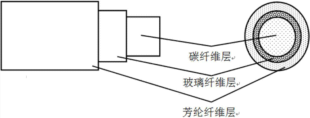

Image

  • Three-layer concentric high-performance fiber composite material cable core rod and manufacturing method thereof
  • Three-layer concentric high-performance fiber composite material cable core rod and manufacturing method thereof

Examples


Embodiment 1

[0035] 1), fix the carbon fiber yarn 1-1, glass fiber yarn 1-2, and aramid fiber yarn 1-3 on the creel 1, and make the yarn bundle pass through the yarn guide plate 2, keep the carbon fiber in the center, and the glass fiber and aramid fiber The fibers are left and right symmetrical, and are distributed on both sides of the carbon fiber from the inside to the outside in order to adjust the tension and prevent the fibers from sagging and winding.

[0036] 2) The above three kinds of fibers are dehumidified through the drying equipment 3, and then enter the glue tank 4 to soak the liquid resin.

[0037] 3) The carbon fiber impregnated with the resin first passes through the first pre-curing mold 5 to form a preformed mandrel of carbon fiber composite material, and the glass fiber and aramid fiber pass through the first dividing plate 6 outside the pre-curing mold 5 .

[0038] 4), passing through the first yarn dividing plate 6 and the first circular yarn collecting plate 7 throu...

Embodiment 2

[0059] A three-layer concentric high-performance fiber composite cable mandrel, the mandrel is an epoxy resin-based composite mandrel containing carbon fiber, glass fiber, and aramid fiber, composed of a carbon fiber inner layer at the inner core position, A glass fiber middle layer coated on the outside of the carbon fiber inner layer, and an aramid fiber outer layer wrapped on the outside of the glass fiber middle layer. In the cross section of the mandrel, the carbon fiber inner layer, the glass fiber middle layer and the The outer circumference of the aramid fiber outer layer is concentric circles. The mandrel includes the following components: 35 parts of carbon fiber, 10 parts of glass fiber, 15 parts of aramid fiber, and 20 parts of resin, in parts by volume. Manufactured by the method described in Example 1.

Embodiment 3

[0061] A three-layer concentric high-performance fiber composite cable mandrel, the mandrel is an epoxy resin-based composite mandrel containing carbon fiber, glass fiber, and aramid fiber, composed of a carbon fiber inner layer at the inner core position, A glass fiber middle layer coated on the outside of the carbon fiber inner layer, and an aramid fiber outer layer wrapped on the outside of the glass fiber middle layer. In the cross section of the mandrel, the carbon fiber inner layer, the glass fiber middle layer and the The outer circumference of the aramid fiber outer layer is concentric circles. The mandrel includes the following components: 45 parts of carbon fiber, 15 parts of glass fiber, 25 parts of aramid fiber, and 45 parts of resin, in parts by volume. Manufactured by the method described in Example 1.


PUM

PropertyMeasurementUnit
Tensile strengthaaaaaaaaaa
Tensile modulusaaaaaaaaaa
Densityaaaaaaaaaa

Abstract

The invention discloses a three-layer concentric high-performance fiber composite material cable core rod and a manufacturing method thereof. The internal layer of the core rod is made of carbon fiber composite material, the intermediate layer is made of glass fiber composite material, and the external layer is made of aramid fiber composite material so that a concentric structure is formed by the three layers. The invention also discloses a manufacturing method of the core rod. Carbon fiber, glass fiber and aramid fiber are infiltrated in liquid resin in an open glue tank; carbon fiber composite material preformed core rod is firstly formed by the impregnated carbon fiber; the impregnated glass fiber evenly wraps the carbon fiber composite material preformed core rod so that a two-layer concentric structured carbon fiber / glass fiber composite material preformed core rod is formed; and aramid fiber through impregnation and online ultrasound processing evenly wraps the carbon fiber / glass fiber composite material preformed core rod so that a three-layer concentric structured carbon fiber / glass fiber / aramid fiber composite material core rod is obtained, and thus the core rod is enabled to possess the characteristics of high strength, high toughness, high insulation, low density and high tensile modulus.

Description

technical field [0001] The invention relates to the field of aerial cables, in particular to a three-layer concentric high-performance fiber composite cable mandrel and a manufacturing method. Background technique [0002] Conductors with carbon fiber reinforced resin-based composite materials as reinforced mandrels (referred to as carbon fiber composite core conductors) have been more and more used in overhead high-voltage power distribution system lines since they were successfully developed by CTC Company in the United States in 2003. Compared with the traditional steel core, the carbon fiber reinforced resin matrix composite core has the characteristics of higher tensile strength, lower density, corrosion resistance and no rust. Therefore, the carbon fiber composite core wire can use soft aluminum as the carrier fluid, which has higher conductivity, thereby reducing the resistance loss of the wire. At the same time, the composite core is almost non-conductive, and there ...

Claims


Application Information

Patent Timeline
IPC IPC(8): H01B7/18H01B13/22H01B9/00
Inventor 郭云力贾玉玺
Owner SHANDONG UNIV
Learn More