Grid-side main circuit of industrial transmission system, transformer and control method
A transmission system and grid-side converter technology, applied in AC network circuits, transformer/inductor coils/windings/connections, circuit devices, etc. Wave size and other problems, to achieve the effect of reducing secondary current harmonics, reducing volume and cost
- Summary
- Abstract
- Description
- Claims
- Application Information
AI Technical Summary
Problems solved by technology
Method used
Image

Examples
Embodiment 1
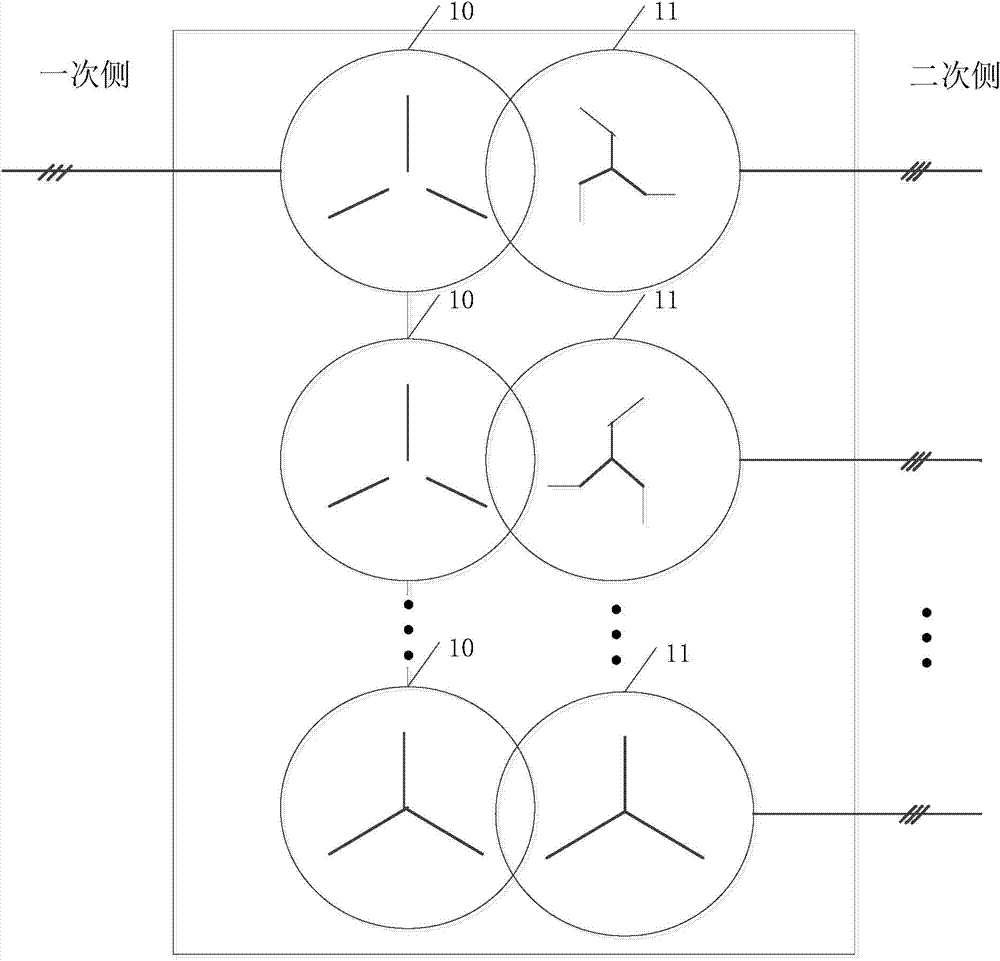
[0041] figure 1 A structural diagram of a transformer provided by the present invention. The transformer is used for the grid-side main circuit of the industrial transmission system and is connected to the AC bus, including: at least two primary windings 10 and at least two secondary windings 11 corresponding to the primary windings 10, the primary The windings 10 are connected in series, the secondary windings 11 are independent and there is a predetermined phase difference between two adjacent secondary windings 11 .
[0042] Such as figure 1 As shown, the transformer includes N primary windings 10 and N secondary windings 11, the N primary windings 10 are in series structure, the N secondary windings 11 are independent, and two adjacent secondary windings 11 There is a predetermined phase difference, that is, the secondary windings 11 are connected to their corresponding primary windings 10 in a phase-staggered manner. When N=2, that is, the transformer has 2 secondary w...
Embodiment 2
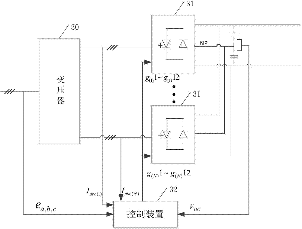
[0053] image 3 It is a structural diagram of a grid-side main circuit of an industrial transmission system provided by the present invention. The grid-side main circuit of the industrial transmission system includes: the transformer 30 as described in Embodiment 1, and also includes: at least two grid-side converters 31 connected to the transformer 30, and one of the grid-side converters 31 is connected to one of the secondary windings;
[0054] A control device 32 connected to the high-voltage side of the transformer 30 and the grid-side converter 31, wherein the control device 32 is connected to the high-voltage side for obtaining a synchronization signal of the high-voltage side of the transformer 30 e a,b,c , the control device 32 is connected to the current input terminal of the grid-side converter 31 for collecting the input current I of the grid-side converter 31 abc(1) ~I abc(N) , the control device 32 is connected to the output terminal NP of the grid-side conver...
Embodiment approach
[0060] As a preferred implementation manner, the three-level diode neutral point clamping converter includes 12 switching devices and 18 diodes;
[0061] Wherein, the control device sends 12 pulse control signals to each of the three-level diode mid-point clamped converters to control the on-off of the 12 switching devices.
[0062] As a preferred implementation manner, the switching device is an insulated gate bipolar transistor IGBT, an electron injection enhanced gate transistor IEGT or an integrated gate commutated thyristor IGCT.
[0063] Figure 4 It is a structural diagram of the grid-side main circuit of another industrial transmission system provided by the present invention. As a preferred embodiment, the control device 32 includes:
[0064] A phase-locked loop 40 connected to the high-voltage side of the transformer 30, a voltage loop regulator 41 connected to the output end of the grid-side converter 31, and an active current regulator 42 connected to the voltage...
PUM
 Abstract
Description
Claims
Application Information
 - R&D
- Intellectual Property
- Life Sciences
- Materials
- Tech Scout
- Unparalleled Data Quality
- Higher Quality Content
- 60% Fewer Hallucinations
Browse by: Latest US Patents, China's latest patents, Technical Efficacy Thesaurus, Application Domain, Technology Topic, Popular Technical Reports.
© 2025 PatSnap. All rights reserved.Legal|Privacy policy|Modern Slavery Act Transparency Statement|Sitemap|About US| Contact US: help@patsnap.com