Waste gas processing method and device collaborating vacuum ultraviolet light catalysis and ozone catalytic oxidation

A technology of ozone catalytic oxidation and waste gas treatment device, which is applied to organic waste gas and stench, can solve the problems of residual ozone, ozone secondary pollution, improper control of ozone concentration, etc., and achieve the effect of avoiding waste of resources, avoiding waste, and simple structure

Active Publication Date: 2015-08-26
深圳科莱环保科技有限公司
View PDF8 Cites 33 Cited by
  • Summary
  • Abstract
  • Description
  • Claims
  • Application Information

AI Technical Summary

Problems solved by technology

[0006] Chinese utility model patent CN202983486U discloses an integrated purification equipment for processing complex industrial organic waste gas, in which an electrostatic precipitator, a photocatalytic reaction device, an ozone generator and an adsorption bed are sequentially arranged in the reaction box. The integrated purification equipment for exhaust gas requires the installation of an ozone generator. The adsorption layer only has the function of absorbing and enriching ozone. Layers also need to be replaced periodically
[0007] Chinese invention patent CNIO3585865A discloses a photo-oxygen purification exhaust gas treatment device, including a microwave generator for filtering particulate matter, an active oxygen ultraviolet lamp, a germicidal ultraviolet lamp, and a plurality of substrates with a photocatalyst coating, wherein the active oxygen ultraviolet lamp It is an ultraviolet lamp that emits ultraviolet light with a wavelength of 185 nanometers. It has the defects of secondary pollution such as residual ozone and intermediate by-products and the inefficient use of ozone resources.
[0008] Chinese invention patent CN1951544A discloses a method and device for photochemically degrading organic gas. The method for oxidizing organic gas by using ozone, ultraviolet rays or ozone plus ultraviolet rays alone has defects such as incomplete oxidation and formation of secondary pollutants of intermediate products. At the same time, ozone Risk of residual ozone due to improper concentration control
[0009] Chinese invention patent CN102247750 discloses a device and method for simultaneous desulfurization and denitration of flue gas by liquid-phase ozone catalytic oxidation method. The device is equipped with an ozone generator, which has high energy consumption and complex structure

Method used


Image

  • Waste gas processing method and device collaborating vacuum ultraviolet light catalysis and ozone catalytic oxidation
  • Waste gas processing method and device collaborating vacuum ultraviolet light catalysis and ozone catalytic oxidation
  • Waste gas processing method and device collaborating vacuum ultraviolet light catalysis and ozone catalytic oxidation

Examples


Embodiment 1

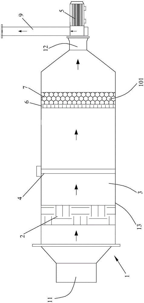
[0046] The embodiment of the exhaust gas treatment device of vacuum ultraviolet photocatalysis and ozone catalytic oxidation of the present invention is as follows figure 1 As shown, the device includes a reactor 1, the reactor 1 has an air inlet 11, an air outlet 12 and a rectangular cylinder 13 in cross section, and a high-efficiency filter 2 and a composite catalyst structure are built in the cylinder 13 along the direction of gas flow , the gas flow direction is also the axial direction of the cylinder 13, the high efficiency filter 2 and the composite catalyst structure are arranged radially along the cylinder 13, and the composite catalyst structure is formed by compounding the photocatalyst layer 6 and the ozone catalyst layer, and the cylinder 13 is in the A photocatalytic chamber 3 is formed in the cavity region between the high-efficiency filter 2 and the composite catalyst structure. In the photocatalytic chamber 3, an ultraviolet lamp 4 is arranged radially along th...

Embodiment 2

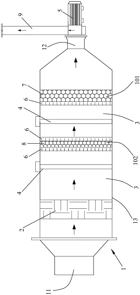
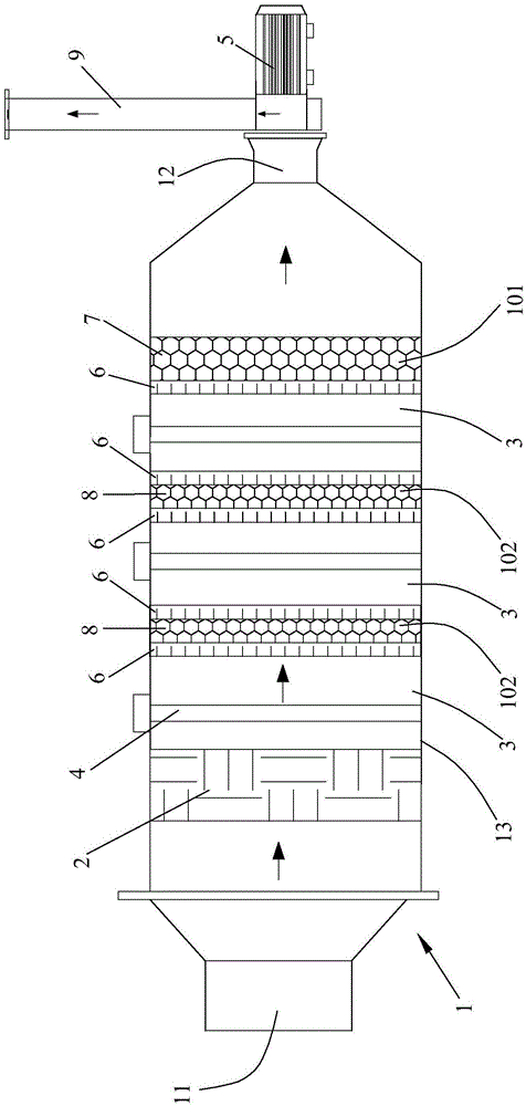
[0057] Embodiment 2 of the exhaust gas treatment device of vacuum ultraviolet light photocatalysis and ozone catalytic oxidation of the present invention is as follows figure 2 As shown, different from Embodiment 1, the composite catalyst structure also includes a middle section composite catalyst unit 102, which is located between the high efficiency filter 2 and the end composite catalyst unit 101, and the cylinder body 13 is positioned at The cavity area between the high-efficiency filter 2 and the terminal composite catalyst unit 101 is divided into two photocatalytic chambers 3, and each photocatalytic chamber 3 is provided with an ultraviolet lamp 4 along the radial direction of the cylinder body 13, and the ultraviolet lamp 4 selects a wavelength It is a 185nm vacuum ultraviolet lamp, and the middle composite catalyst unit 102 is arranged radially along the cylinder body 13. The middle composite catalyst unit 102 is composed of two layers of photocatalyst layers 6 and o...

example 1

[0070] Exhaust gas parameters: flow rate 800-1000m 3 / h, the pollutant components are benzene and benzene series, the concentration is 30-50ppm, the relative humidity is 50%, and the temperature is 25-35°C.

[0071] When the exhaust gas treatment device is running, the fan and vacuum ultraviolet lamp are turned on by controlling the electric control box. After the organic waste gas passes through the high-efficiency filter layer to remove impurities such as particulate matter, it enters the vacuum ultraviolet photocatalytic chamber. In the gas phase reaction, benzene and benzene series are completely degraded into CO 2 And water, and form ozone. When the undegraded benzene and benzene series and ozone pass through the photocatalyst-ozone catalyst-photocatalyst layer, they are further oxidized into CO by photocatalytic oxidation and ozone catalytic oxidation. 2 And water, and finally pass through the ozone catalyst layer again, further complete ozone catalytic oxidation of rem...


PUM


Abstract

The invention discloses a waste gas processing method and device collaborating vacuum ultraviolet light catalysis with ozone catalytic oxidation. The waste gas processing method comprises the following steps: after particulate impurities in waste gas are removed, the waster gas enters a vacuum ultraviolet light catalysis chamber; a pollutant is directly split by the ultraviolet light emitted by an ultraviolet lamp, and free radicals with high oxidizability and ozone substances are generated at the same time so as to further oxidize the pollutant; in a composite catalyst structure formed by compounding a photocatalyst layer and an ozone catalyst layer, the residual pollutant is further purified through the collaboration of vacuum ultraviolet light catalysis and ozone catalytic oxidation, and the ozone is totally utilized and eliminated at the same time. The waste gas processing device comprises a reactor, wherein an efficient filter and the composite catalyst structure are arranged in the reactor; the composite catalyst structure is formed by compounding the photocatalyst layer and the ozone catalyst layer; the light catalysis chamber is formed at the inner cavity zone between the efficient filter and the composite catalyst structure, and the ultraviolet lamp is arranged in the light catalysis chamber. The waste gas is purified by utilizing the collaboration of vacuum ultraviolet light catalysis and ozone catalytic oxidation.

Description

technical field [0001] The invention belongs to organic waste gas, stench, SO 2 and NO X The field of treatment technology specifically refers to a waste gas treatment method and device for vacuum ultraviolet photocatalysis and ozone catalytic oxidation. Background technique [0002] With the rapid development of industry and the continuous consumption of resources and energy, atmospheric environmental problems have become increasingly prominent. In the past, people were familiar with sulfur dioxide, nitrogen oxides, and volatile organic compounds (VOC) were important pollutants that were neglected in the past. Although volatile organic compounds do not directly form PM2.5, they will form PM2.5 through photochemical reactions. They are one of the important precursors for the formation of smog. The types are complex and involve many industries. They also widely exist in indoor living environments and human activities. process. [0003] At present, VOCs governance has attr...

Claims


Application Information

Patent Timeline
Patent Type & Authority Applications(China)
IPC IPC(8): B01D53/75B01D53/86B01D53/74B01D53/76B01D53/60B01D53/44B01D46/00
Inventor 黄海保叶信国
Owner 深圳科莱环保科技有限公司
Why Eureka
Try Eureka