Broadband photon sieve based on wavefront coding technology
A wavefront coding, photonic sieve technology, applied in optics, optical components, diffraction gratings, etc., can solve problems such as low diffraction efficiency
- Summary
- Abstract
- Description
- Claims
- Application Information
AI Technical Summary
Problems solved by technology
Method used
Image
Examples
Embodiment 1
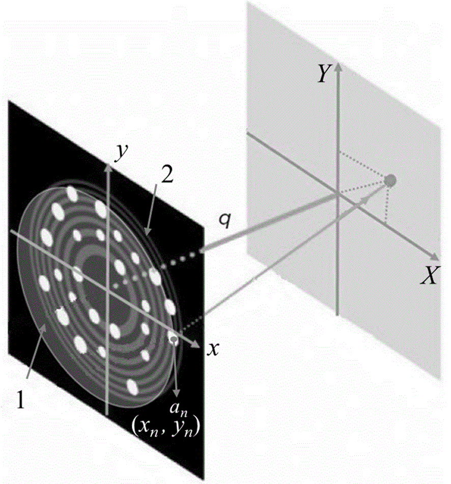
[0030] Embodiment one: see attached figure 1 As shown, a broadband photon sieve based on wavefront encoding technology has a phase encoding plate, one surface of the phase encoding plate is a phase encoding surface 1, and the other surface is a plane, and there is a photon sieve 2 behind the plane, The phase encoding surface 1 is a cubic encoding surface, and the photon sieve diffracts the light passing through the cubic encoding surface for imaging.
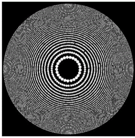
[0031] The material of the phase encoding plate can be selected from PMMA plexiglass, and the back is close to the photon sieve surface. photon sieve attached figure 2 As shown, assuming that the incident light is parallel light, the incident light first passes through the phase encoding surface, and then is diffracted by the photon sieve surface to form an image.
[0032] The imaging principle is as follows:
[0033] The diffraction field of the photon sieve is formed by the superposition of the diffraction fields of all mi...
Embodiment 2
[0063] Embodiment 2: A broadband photon sieve based on wavefront encoding technology has a phase encoding plate, one surface of the phase encoding plate is a phase encoding surface, and the other surface is a plane, and the photon sieve is closely attached to the plane , the phase encoding surface is a logarithmic encoding surface, and the surface shape function of the logarithmic encoding surface is , where, , α is 40π, and β is 0.4, and the photon sieve diffracts the light passing through the phase encoding surface into an image.
[0064] The broadband photonic sieve of this embodiment was prepared with a diameter of 50 mm and a focal length of 500 mm. After testing, the bandwidth of the photon sieve was about 14 nm.
Embodiment 3
[0065] Embodiment 3: A broadband photon sieve based on wavefront encoding technology, has a phase encoding plate, one surface of the phase encoding plate is a phase encoding surface, and the other surface is a plane, and a photon sieve is attached to the plane behind , the phase encoding surface is an index encoding surface, and the surface shape function of the index encoding surface is , where, , α is 10π, β is 1.2, and the photon sieve diffracts the light passing through the phase encoding surface into an image.
[0066] The broadband photonic sieve of this embodiment was prepared with a diameter of 50 mm and a focal length of 500 mm. After testing, the bandwidth of the photon sieve was about 14 nm.
PUM
 Abstract
Description
Claims
Application Information
 - R&D
- Intellectual Property
- Life Sciences
- Materials
- Tech Scout
- Unparalleled Data Quality
- Higher Quality Content
- 60% Fewer Hallucinations
Browse by: Latest US Patents, China's latest patents, Technical Efficacy Thesaurus, Application Domain, Technology Topic, Popular Technical Reports.
© 2025 PatSnap. All rights reserved.Legal|Privacy policy|Modern Slavery Act Transparency Statement|Sitemap|About US| Contact US: help@patsnap.com


