Optical assembly for being vertically coupled with photoelectric transceiving array and manufacturing method

An optical component, photoelectric transceiver technology, applied in optical components, optical waveguide coupling, optics, etc., can solve the problems of easy damage, unusability, and fiber breakage of optical fibers, and achieve high pass rate, high reflection accuracy, and easy processing Effect

Active Publication Date: 2015-08-26
FENGHUO COMM SCI & TECH CO LTD
View PDF7 Cites 8 Cited by
  • Summary
  • Abstract
  • Description
  • Claims
  • Application Information

AI Technical Summary

Problems solved by technology

[0006] The purpose of the present invention is to overcome the shortcomings of the above-mentioned background technology, provide an optical component and a manufacturing method for vertical coupling with the photoelectric transceiver array, realize the optical path angle through the reflective prism, and avoid damaging the output end face of the arrayed waveguide grating chip, or The outpu

Method used


Image

  • Optical assembly for being vertically coupled with photoelectric transceiving array and manufacturing method
  • Optical assembly for being vertically coupled with photoelectric transceiving array and manufacturing method
  • Optical assembly for being vertically coupled with photoelectric transceiving array and manufacturing method

Examples


Embodiment 1

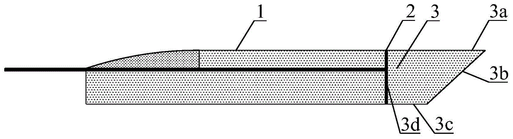
[0037] see figure 1 As shown, Embodiment 1 provides an optical assembly for vertical coupling with an optoelectronic transceiver array, the optical assembly includes a multi-core optical fiber array 1 and a reflective prism 3 . The reflective prism 3 is a right-angled trapezoidal prism, which includes an upper bottom surface 3c, a lower bottom surface 3a, a right-angled waist surface 3d and an oblique waist surface 3b, and the angle between the oblique waist surface 3b and the lower bottom surface 3a is 41°~45°, and the right-angle waist surface The height of the surface 3d is equal to the height of the multi-core optical fiber array 1, and is connected to the multi-core optical fiber array 1 by an adhesive 2. The right-angled trapezoidal prism can be set upright or upside down. In this embodiment, the right-angled trapezoidal prism is set upside down. .

[0038] Adhesive 2 is shadowless glue, such as acrylate. The adhesive 2, the reflective prism 3 and the multi-core optica...

Embodiment 2

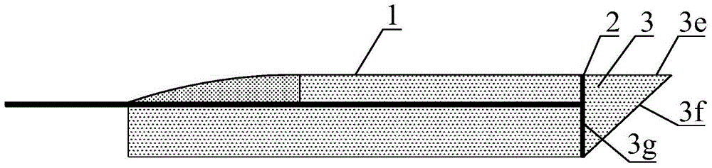
[0046] see figure 2 As shown, Embodiment 2 provides an optical assembly for vertical coupling with a photoelectric transceiver array, the optical assembly includes a multi-core optical fiber array 1 and a reflective prism 3 . Reflecting prism 3 is a right-angled triangular prism, which includes a first right-angled surface 3e, a second right-angled surface 3g and an inclined surface 3f, the angle between the first right-angled surface 3e and the inclined-plane 3f is 41°~45°, and the second right-angled surface 3g The height is equal to the height of the multi-core optical fiber array 1, and is connected to the multi-core optical fiber array 1 through the adhesive 2, the first rectangular surface 3e can be located above the slope 3f, and can also be located above the slope 3f, in this embodiment, The first right-angled surface 3e is located above the inclined surface 3f.

[0047] Adhesive 2 is shadowless glue, such as acrylate. The adhesive 2, the reflective prism 3 and the ...

Embodiment 3

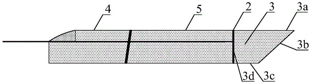
[0055] see image 3 As shown, Embodiment 3 provides an optical assembly for vertical coupling with an optoelectronic transceiver array, the optical assembly includes an arrayed waveguide grating chip 5 and a reflective prism 3 . The reflective prism 3 is a right-angled trapezoidal prism, which includes an upper bottom surface 3c, a lower bottom surface 3a, a right-angled waist surface 3d and an oblique waist surface 3b, and the angle between the oblique waist surface 3b and the lower bottom surface 3a is 41°~45°, and the right-angle waist surface The height of the surface 3d is equal to the height of the arrayed waveguide grating chip 5, and is connected to the arrayed waveguide grating chip 5 through the adhesive 2. The right-angled trapezoidal prism can be set upright or upside down. In this embodiment, the right-angled trapezoidal prism is set upside down. .

[0056] Adhesive 2 is shadowless glue, such as acrylate. In this embodiment, the arrayed waveguide grating chip 5 ...


PUM


Abstract

The invention discloses an optical assembly for being vertically coupled with a photoelectric transceiving array and a manufacturing method, relating to the field of optical fiber communication. The optical assembly comprises an optical signal transmission device and a reflecting prism, wherein the optical signal transmission device is a multi-core optical fiber array or an array waveguide grating chip; the reflecting prism is a right trapezoid prism or a right triangle prism; the optical signal transmission device is connected with the reflecting prism through an adhesive. Rotation of a light path is realized through the reflecting prism, so that the output end face of the array waveguide grating chip or the output end face of the optical fiber array can be avoided, and the problem that the optical fiber is broken and the ground optical fiber in the later using stage is easily damaged and cannot be used when the optical fiber is ground is solved. According to the optical assembly, large-scaled production is easy and the yield is relatively high. The vertical coupling efficiency between the optical assembly and the photoelectric transceiving array can be effectively improved.

Description

technical field [0001] The invention relates to the field of optical fiber communication, in particular to an optical component for vertical coupling with a photoelectric transceiver array and a manufacturing method. Background technique [0002] With the development of optical transmission research, wavelength division multiplexing technology has become an effective means to increase the capacity of communication information. Wavelength division multiplexing refers to the transmission of multiple wavelengths into the same waveguide or optical fiber of the optical line. Demultiplexing refers to the technology of separating the total light in a waveguide or optical fiber by wavelength. Arrayed waveguide grating is the realization of An ideal device for wavelength division multiplexing / demultiplexing, it can be coupled with the optical channel of the photoelectric transceiver array to realize the mutual conversion of optical signals and electrical signals. At present, the ver...

Claims


Application Information

Patent Timeline
IPC IPC(8): G02B6/42
CPCG02B6/42G02B6/4214G02B6/4201
Inventor 黄美金谭国华
Owner FENGHUO COMM SCI & TECH CO LTD
Why Eureka
Try Eureka