Concentrator photovoltaic conversion device and manufacturing method thereof
A photoelectric conversion device and manufacturing method technology, applied in photovoltaic power generation, final product manufacturing, sustainable manufacturing/processing, etc., capable of solving problems such as inability to obtain power generation
- Summary
- Abstract
- Description
- Claims
- Application Information
AI Technical Summary
Problems solved by technology
Method used
Image

Examples
Embodiment 1
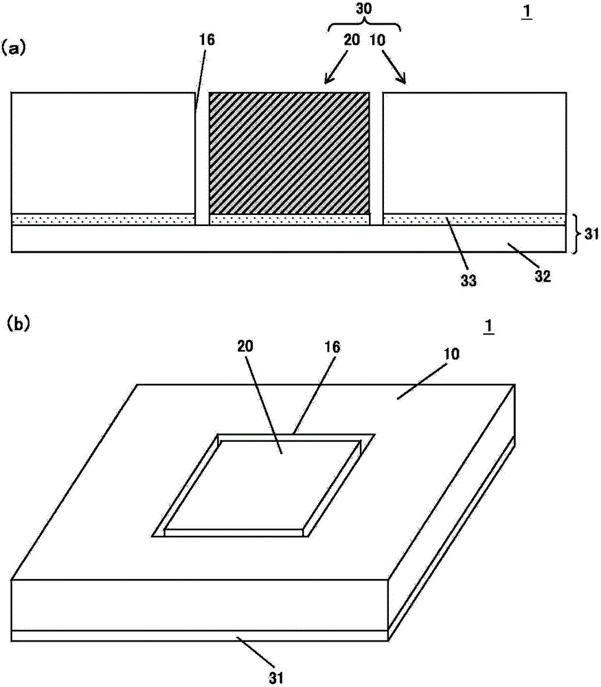
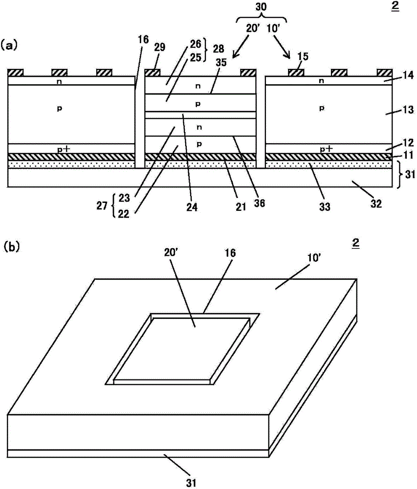
[0201] First, a silicon solar cell 10' having through holes 16 formed by an etching method is prepared.
[0202] Next, using solder paste, the silicon solar cell 10' and the III-V group multi-junction solar cell 20' are placed on the external connection substrate 31, that is, the PCB substrate. The III-V group multi-junction solar cell 20' is mounted It is placed in the through hole 16 part of the silicon solar cell 10'.
[0203] Next, UV ozone treatment is applied.
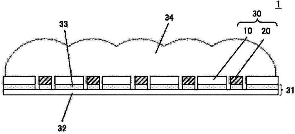
[0204] Next, the photoelectric conversion element 30 and the external connection substrate 31 are placed in a mold, and a silicone resin (LPS-3541 (model): manufactured by Shin-Etsu Chemical Co., Ltd.) is compression molded to form The condenser lens 34 is integrally molded to manufacture the condenser type photoelectric conversion device 2.
Embodiment 2
[0206] First, a silicon solar cell 10' having through holes 16 formed by an etching method is prepared.
[0207] Next, using solder paste, the silicon solar cell 10' and the III-V group multi-junction solar cell 20' are placed on the external connection substrate 31, that is, the PCB substrate. The III-V group multi-junction solar cell 20' is mounted It is placed in the through hole 16 part of the silicon solar cell 10'.
[0208] Next, UV ozone treatment is performed.
[0209] Next, using a vacuum laminating device (manufactured by Nichigo-Morton), a resin film made by mixing silicone resin (AF-500 (model): manufactured by Shin-Etsu Chemical Industry) and phosphor is attached to the silicon solar cell 10' s surface.
[0210] Next, the photoelectric conversion element 30 connected to the external connection substrate 31 is placed in a mold, and a silicone resin (LPS-3541 (model): manufactured by Shin-Etsu Chemical Co., Ltd.) is compression molded to integrally mold the condenser 34 to...
Embodiment 3
[0212] First, a silicon solar cell 10' having through holes 16 formed by an etching method is prepared.
[0213] Next, using solder paste, the silicon solar cell 10' and the III-V group multi-junction solar cell 20' are placed on the external connection substrate 31, that is, the PCB substrate. The III-V group multi-junction solar cell 20' is mounted It is placed in the through hole 16 part of the silicon solar cell 10'.
[0214] Next, UV ozone treatment is performed.
[0215] Next, by spin coating, the surface of the silicon solar cell 10' is coated with a mixture of polysilazane and phosphor, and then cured to form a vitreous layer.
[0216] Next, the photoelectric conversion element 30 connected to the external connection substrate 31 is placed in a mold, and a silicone resin (LPS-3541 (model): manufactured by Shin-Etsu Chemical Co., Ltd.) is compression molded to integrally mold the condenser 34 to produce a poly Light-type photoelectric conversion device 2.
PUM
 Abstract
Description
Claims
Application Information
 - R&D
- Intellectual Property
- Life Sciences
- Materials
- Tech Scout
- Unparalleled Data Quality
- Higher Quality Content
- 60% Fewer Hallucinations
Browse by: Latest US Patents, China's latest patents, Technical Efficacy Thesaurus, Application Domain, Technology Topic, Popular Technical Reports.
© 2025 PatSnap. All rights reserved.Legal|Privacy policy|Modern Slavery Act Transparency Statement|Sitemap|About US| Contact US: help@patsnap.com