Safe monitoring and protection device for drilling and intelligent protection system of safe monitoring and protection device

A technology of safety monitoring and safety protection, which is applied to the automatic control system of drilling, drilling equipment, earthwork drilling and mining, etc., can solve the problems of failure to meet the standards and actual work requirements on site, easy deformation of positioning pins, shear force, and injury of on-site staff To meet the needs of oilfield exploration and development, ensure the safety of life and property, and reduce downhole risks

Active Publication Date: 2015-09-02
PUYANG BAIFU REIDE PETROLEUM SCI & TECH CO LTD
View PDF8 Cites 16 Cited by
  • Summary
  • Abstract
  • Description
  • Claims
  • Application Information

AI Technical Summary

Problems solved by technology

[0007] 1) No automatic pump stop function: the drilling pump is still running after the safety valve works and the pressure is released, and the pump can only be stopped after the operator finds out, causing a large amount of mud to overflow, which may cause injury to the on-site staff and cause environmental pollution;
[0008] 2) The positioning pin is easily deformed, resulting in an increase in the error of the shear force, causing the safety valve to release pressure in advance or lagging behind to cause an accident;
[0009] 3) The calibration value of the positioning pin is only 5-6, which cannot meet the standard and the actual work requirements on site;
[0010] 4) If the safety valve is not maintained in time, it will easily lead to rust and jam, and it will not work normally when the pump pressure is out of control;
[0011] 5) The interval between restarting the drilling pump after pressure relief is long
In actual use, neither of the above two methods c

Method used


Image

  • Safe monitoring and protection device for drilling and intelligent protection system of safe monitoring and protection device
  • Safe monitoring and protection device for drilling and intelligent protection system of safe monitoring and protection device
  • Safe monitoring and protection device for drilling and intelligent protection system of safe monitoring and protection device

Examples


Embodiment 1

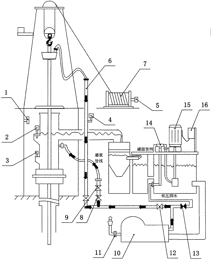
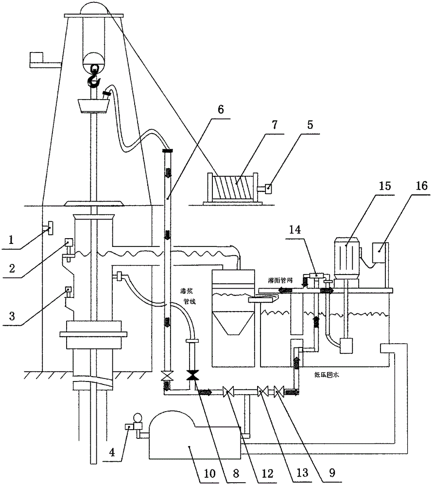
[0085] see figure 1 , figure 2 or image 3 The drilling safety monitoring and protection device of the present invention includes a data acquisition unit, a control processing unit, and a safety protection execution unit. The control processing unit includes a PLC and an industrial computer. The PLC is connected to the industrial computer through a serial port, and each of the data acquisition units After real-time collection of on-site operation data by sensors, the AD module converts it and transmits it to the PLC and the industrial computer. The industrial computer judges whether to take safety protection measures according to the preset program, and starts the safety protection execution unit through the PLC. The safety protection execution unit The unit includes an electronically controlled pump pressure protection mechanism and a multifunctional traveling block protection mechanism, and the configuration of the corresponding data acquisition unit includes: installed in...

Embodiment 2

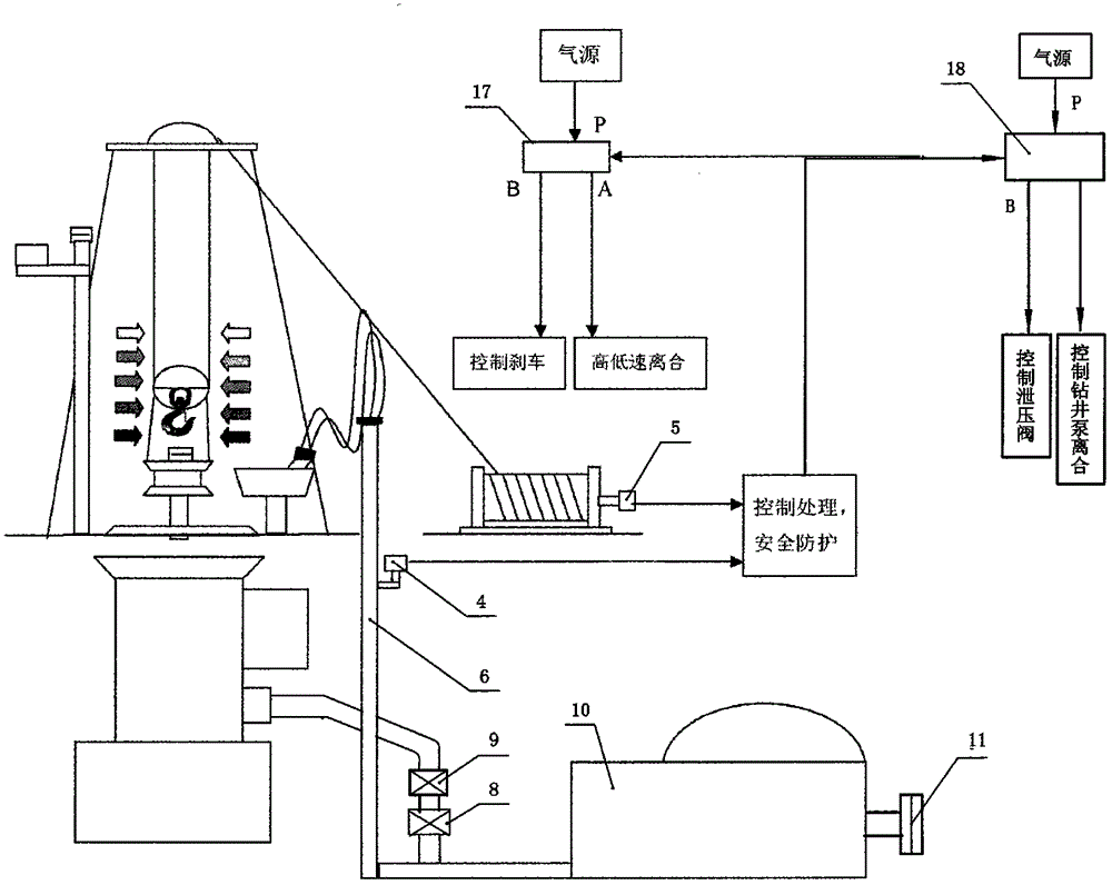
[0088] see figure 1 , figure 2 or image 3 , Figure 4 . The drilling safety monitoring and protection device of this embodiment is different from Embodiment 1 in that the configuration of the electronically controlled pump pressure protection mechanism is as follows:

[0089] 1) Install a normally closed pneumatic valve downstream of the grouting valve or the low pressure return valve of the high pressure pipeline;

[0090] 2) For mechanical drilling pumps, a normally open pump pressure protection solenoid valve 18 is installed on the air circuit between the drilling pump control switches. The pump pressure protection solenoid valve 18 adopts a two-position five-way solenoid valve. The inlet P of the valve 18 is connected to the control air source, and the normally open outlet A of the pump pressure protection solenoid valve is divided into two paths, one path is connected to the inlet gas path of the manual switch valve of the drilling pump, and the other path is connec...

Embodiment 3

[0096] see figure 1 , figure 2 or image 3 , Figure 5 . The drilling safety monitoring and protection device of this embodiment is different from Embodiment 2 in that the configuration of the electronically controlled pump pressure protection mechanism is as follows:

[0097] For mechanical drilling pumps, a normally open pump pressure protection solenoid valve 18 is installed on the outlet gas path of the manual switch valve of the drilling pump. The pump pressure protection solenoid valve 18 adopts a two-position five-way solenoid valve, and the pump pressure protection solenoid valve The inlet P of 18 is connected with the outlet of the manual on-off valve of the drilling pump, the normally open outlet A of the pump pressure protection solenoid valve 18 is connected with the drilling pump control air circuit, and the normally closed outlet B is blocked; A normally open pressure relief protection solenoid valve 19 is installed between the pressure valve control air cir...


PUM


Abstract

The invention relates to the technical field of petroleum drilling safety, in particular to a safe monitoring and protection device for drilling and an intelligent protection system of the safe monitoring and protection device. The safe monitoring and protection device for drilling comprises a data acquisition unit, a control processing unit and a safe protection execution unit; the control processing unit comprises an PLC (programmable logic controller) and an industrial personal computer, the PLC is connected with the industrial personal computer through a serial port; various kinds of sensors of the data acquisition unit acquire on-site operation data and transmit the data to the PLC and the industrial personal computer in real time; the safe protection execution unit comprises a pumping pressure protection mechanism and a runner wagon protection mechanism; a pressure sensor mounted on a vertical pipe or a slurry pump, a winch sensor mounted on a winch barrel and a weight transducer mounted on a deadline anchor output signals to be connected with the PLC; the PLC is in control connection with the pumping pressure protection mechanism and the runner wagon protection mechanism. According to the safe monitoring and intelligent protection device for drilling, the safe protection execution unit comprises a pumping pressure protection sub-system which mainly adopts an active response type safe protection method, and when pumping pressure reaches a set protection value, the pump stops firstly and then pressure relief is performed.

Description

technical field [0001] The invention relates to oil drilling safety monitoring and protection technology, in particular to a drilling safety monitoring and protection device and an intelligent protection system, which is applied to oil drilling and has certain practical significance for reducing the risk of oil drilling and ensuring the safety of people's lives and properties . Background technique [0002] The oil drilling industry is one of the high-risk sub-sectors of the oil industry. There have been some major safety accidents in oil drilling in history, which not only caused heavy economic losses, but also had huge negative social impacts. Especially in recent years, with the rapid development of the domestic oil industry and the rapid expansion of oil drilling teams, tripping out of drilling and grouting is not timely, overflow and lost circulation monitoring is not accurate, traveling car tops the crane, pauses drilling, slides drilling, and lost circulation Can no...

Claims


Application Information

Patent Timeline
IPC IPC(8): E21B44/00
Inventor 赵刚曹民于春夏玉龙
Owner PUYANG BAIFU REIDE PETROLEUM SCI & TECH CO LTD
Why Eureka
Try Eureka