Radial radiating beam electron gun suitable for radial logarithmic spiral microstrip slow-wave line

A technology of logarithmic spiral and slow wave line, which is applied in the field of vacuum electronic devices to achieve the effects of not easy to fall off or drop, low manufacturing cost and high working voltage

Inactive Publication Date: 2015-09-09
UNIV OF ELECTRONIC SCI & TECH OF CHINA
View PDF3 Cites 4 Cited by
  • Summary
  • Abstract
  • Description
  • Claims
  • Application Information

AI Technical Summary

Problems solved by technology

[0007] The purpose of the present invention is to provide a technical problem that the existing electron gun and the radial logarithmic spiral microstrip slow wave line that uses the planar fan-shaped electron beam can not be synchronized well in the prior art. The radia

Method used


Image

  • Radial radiating beam electron gun suitable for radial logarithmic spiral microstrip slow-wave line
  • Radial radiating beam electron gun suitable for radial logarithmic spiral microstrip slow-wave line
  • Radial radiating beam electron gun suitable for radial logarithmic spiral microstrip slow-wave line

Examples


Embodiment 1

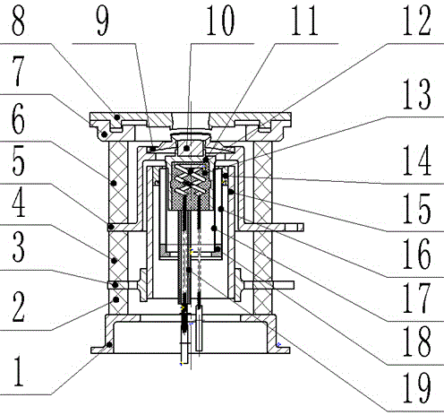
[0041] A radially diverging electron injection gun suitable for radial logarithmic spiral microstrip slow wave lines, the electron gun and the background technology application number is 201210409251.6, the name is "a radial logarithmic spiral microstrip slow wave line" invention Complementary use with the patent pending slow wave line. The electron gun includes a gun casing, and a cathode assembly, a control electrode 9 and an anode 8 are arranged in the gun casing. The anode 8 has a disk-shaped structure, and a radial hole is opened in the middle of the disk of the anode 8 , and the angle of the radial hole of the anode 8 is determined by the radial opening angle of the cathode head 10 . The control pole 9 is also a disc-shaped structure, and a radial hole is opened in the middle of the disc of the control pole 9. When the cathode assembly and the control pole 9 are assembled, the cathode head 10 of the cathode assembly is placed in the radial hole of the control pole 9 Ins...

Embodiment 2

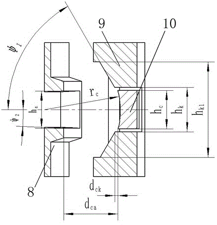
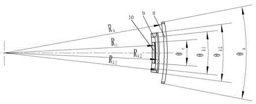
[0045] On the basis of Embodiment 1, the axial width h of the cathode head 10 c =0.6 mm, the axial width h of the radial hole of the control pole 9 k =1.6mm, the axial width h of the opening step of the control pole 9 k1 =0.7mm, the axial width h of the axial opening of the anode 8 a =0.46mm, the distance d between the end face of the cathode head 10 on the side close to the anode 8 and the end of the radial hole of the control electrode 9 on the side close to the anode 8 ck =0.05mm, the distance d between the cathode tip 10 and the anode 8 ca =0.7mm, the cathode emission surface of the cathode head 10 is a cylindrical emission surface, and the radius of curvature r of the cathode emission surface of the cathode head 10 c →∞, the inclination angle ψ of the inner angle of the radial hole of the control pole 9 to the slopes on the left and right sides 91 1 =60°, the inclination angle ψ of the slope protrusions 91 on the upper and lower sides in the radial hole of the control...

Embodiment 3

[0049] On the basis of Embodiment 1, the axial width h of the cathode head 10 c =0.6mm, the axial width h of the radial hole of the control pole 9 k =0.6mm, the axial width h of the opening step of the control pole 9 k1 =0.7mm, the axial width h of the axial opening of the anode 8 a =0.58mm, the distance d between the end face of the cathode head 10 on the side close to the anode 8 and the end of the radial hole of the control electrode 9 on the side close to the anode 8 ck =0.05mm, the distance d between the cathode tip 10 and the anode 8 ca =0.45mm, the cathode emission surface of the cathode head 10 is a hyperboloid emission surface, and the radius of curvature r of the cathode emission surface of the cathode head 10 c = 1.19mm, the inclination angle ψ 1 =60°, the inclination angle ψ of the slope protrusions 91 on the upper and lower sides in the radial hole of the control pole 9 3 =45°, the inclination angle ψ of the radial hole of the anode 8 2 =3°; in the angular s...


PUM


Abstract

The invention discloses a radial radiating beam electronic gun suitable for radial logarithmic spiral microstrip slow-wave lines, and is an electronic gun in the technical field of vacuum electronic devices. The radial radiating beam electronic gun suitable for radial logarithmic spiral microstrip slow-wave lines ensures better synchronization with radial logarithmic spiral microstrip slow-wave lines employing planar sector electron beams for working. The radial radiating beam electronic gun comprises a gun casing, and a cathode assembly, a control electrode and an anode arranged in the gun casing, wherein the cathode head of the cathode assembly is placed in a radial hole in the control electrode. The invention is especially for a radial radiating beam electron gun cooperatively used with radial logarithmic spiral microstrip slow-wave lines.

Description

technical field [0001] The invention belongs to the technical field of vacuum electronic devices, and relates to an electron gun, in particular to a radially divergent electron injection gun suitable for radial logarithmic spiral microstrip slow wave lines. Background technique [0002] Traveling wave tube is the most important type of microwave power amplifier in the field of vacuum microwave electronics. It has the characteristics of high power, high efficiency, high gain, wide frequency bandwidth and long life, so it is widely used in radar, guidance, interference, communication , microwave remote sensing, radiation measurement and other fields, its performance directly determines the level of equipment. [0003] A typical traveling wave tube consists of five parts: electron gun, focusing system, slow wave line (slow wave structure), input and output devices and collector. As the core component of the traveling wave tube, the task of the slow wave line is to transmit th...

Claims


Application Information

Patent Timeline
IPC IPC(8): H01J29/48H01J29/02H01J29/04
CPCH01J29/02H01J29/04H01J29/48H01J29/484H01J29/485
Inventor 宫玉彬李新义王战亮魏彦玉段兆云徐进
Owner UNIV OF ELECTRONIC SCI & TECH OF CHINA
Why Eureka
Try Eureka