Ultrasonic wave-electrical resistance composite welding method

A hybrid welding and ultrasonic technology, applied in the field of welding manufacturing, can solve problems such as limited welding application range, and achieve the effects of reducing welding defects, eliminating pores, and reducing indentation

Inactive Publication Date: 2015-09-16
DALIAN UNIV OF TECH
View PDF7 Cites 14 Cited by
  • Summary
  • Abstract
  • Description
  • Claims
  • Application Information

AI Technical Summary

Problems solved by technology

However, the welding application of this method is limited, it is only suitable for spot welding, and the thickness of the welding plate is only 0.05-0.3mm, and it needs insulating materials to assist metal sheet welding

Method used


Image

  • Ultrasonic wave-electrical resistance composite welding method

Examples


Embodiment 1

[0029] Adopt welding 6061 aluminum alloy structural part of the present invention, the plate thickness of workpiece 3 to be welded is 1mm, and preparation method comprises the following steps:

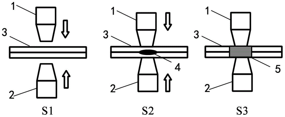
[0030] The upper electrode welding head 1 and the lower electrode welding head 2 shared by resistance / ultrasonic are used to keep the welding contact surface of the workpiece 3 to be welded in contact and ensure the contact resistance required by the welding process; the upper electrode welding head 1 and the lower electrode welding head The current is connected between 2, and the upper electrode welding head 1 and the lower electrode welding head 2 apply ultrasonic waves on the surface of the workpiece 3 to be welded. The welding parameters are: the pressure of the upper electrode welding head 1 and the lower electrode welding head 2 is 3kN, and the welding current DC 20kA, resistance welding maintenance time 1s, ultrasonic frequency 20kHz, amplitude 20μm; resistance welding pressure a...

Embodiment 2

[0032] Adopt the welding AZ31 magnesium alloy structural part of the present invention, the plate material thickness of workpiece 3 to be welded is 1.5mm, and preparation method comprises the following steps:

[0033] The upper electrode welding head 1 and the lower electrode welding head 2 shared by resistance / ultrasonic are used to keep the welding contact surface of the workpiece 3 to be welded in contact and ensure the contact resistance required by the welding process; the upper electrode welding head 1 and the lower electrode welding head Connect the current between 2, and at the same time, the upper electrode welding head 1 and the lower electrode welding head 2 apply ultrasonic waves on the surface of the workpiece 3 to be welded. The welding parameters are: the pressure of the upper electrode welding head 1 and the lower electrode welding head 2 is 3.5kN, and the welding The current is DC 15kA, the resistance welding duration is 1.5s, the ultrasonic frequency is 15kHz,...


PUM

PropertyMeasurementUnit
thicknessaaaaaaaaaa
thicknessaaaaaaaaaa
thicknessaaaaaaaaaa

Abstract

The invention discloses an ultrasonic wave-electrical resistance composite welding method, wherein the method comprises that, at the pre-pressing stage, a welding contact face of a workpiece to be welded is maintained to be contacted; upper and lower electrode welding heads are respectively set at two sides of the workpiece to be welded and the electrode welding heads are maintained at the same shaft; the electrode welding heads are shared by the electrical resistance welding and the ultrasonic wave welding for use; at the welding stage, current is communicated between the electrode welding heads while applying ultrasonic wave; the vibration and friction heat produced by the electrical resistance heat and ultrasonic wave are utilized to heat the workpiece to be welded to reach at a molten state to form a molten core; at the cooling crystallization stage, after the size of the molten core of the workpiece to be welded reaches at a preset size, the pressure of the electrode welding heads are maintained constantly; the electrical resistance welding current and the ultrasonic wave are stopped; or the electrical resistance welding current is cut off, after the ultrasonic wave works until the preset time; and until the liquid state metal is cooled to form a welding spot / a welding joint. According to the invention, the contact between workpieces to be welded is increased by utilizing the high frequency vibration produced by the ultrasonic wave; and the indentation welding defects are reduced, thus the mechanical property of a welding joint is improved.

Description

technical field [0001] The invention belongs to the field of welding manufacturing technology, in particular to an ultrasonic-resistance composite welding method. Background technique [0002] At present, resistance spot welding is one of the most widely used welding methods in aviation, aerospace, and automobile manufacturing industries. However, for lightweight materials such as high-strength steel, aluminum alloys, magnesium alloys, and titanium alloys, the quality of resistance spot welding limits its application. One of the bottlenecks. Taking automobile manufacturing as an example, in order to ensure the reliability of automobiles, the actual number of welds is 30% higher than the design. High-quality and efficient resistance spot welding technology can save a lot of production costs, so the replacement of resistance welding technology and equipment has important practical applications significance. [0003] Aluminum alloy is one of the important lightweight material...

Claims


Application Information

Patent Timeline
Patent Type & Authority Applications(China)
IPC IPC(8): B23K28/02B23K101/18
CPCB23K28/02B23K2101/18
Inventor 任大鑫赵坤民常颖李晓东潘敏
Owner DALIAN UNIV OF TECH
Why Eureka
Try Eureka