High-speed test system and processing method thereof for ATE machine

A test system and machine technology, applied in the direction of measuring electricity, measuring devices, measuring electrical variables, etc., can solve the problems of lack of maintainability, waste of resources in the test system, short-circuiting and virtual welding in manual welding, and reduce Development cost and cycle, guaranteed reuse and maintenance, and improved high-speed signal integrity

Inactive Publication Date: 2015-09-16
NO 771 INST OF NO 9 RES INST CHINA AEROSPACE SCI & TECH
View PDF4 Cites 3 Cited by
  • Summary
  • Abstract
  • Description
  • Claims
  • Application Information

AI Technical Summary

Problems solved by technology

[0003] like figure 1 As shown, firstly, the device under test needs to be connected to the resources of the ATE machine through the socket, the daughter board, the welding cable, and the mother board. , not only seriously affects the assembly and welding cycle of the test system, but also causes serious signal link impedance mismatch, which cannot guarantee the high-speed signal integrity of the ATE test system, and limits the test performance of the ATE machine; secondly, the existing ATE test The size of the system sub-board is generally on the order of half a meter, while the thickness of the test board is only on the order of millimeters. This shape and structure will cause serious deformation of the test board after a certain period of use, and manual welding is also prone to short circuits, False soldering and other problems make the reliability of the test board and signal quality unable to be guaranteed for a long time; finally, limited by the lack of replacement products on the market, when the motherboard or welding cables in the test system are damaged, only the original equipment can be purchased for repair. Replacement, resulting in waste of test system resources, no maintainability

Method used


Image

  • High-speed test system and processing method thereof for ATE machine
  • High-speed test system and processing method thereof for ATE machine
  • High-speed test system and processing method thereof for ATE machine

Examples


Embodiment Construction

[0037] The present invention will be described in further detail below in conjunction with the accompanying drawings.

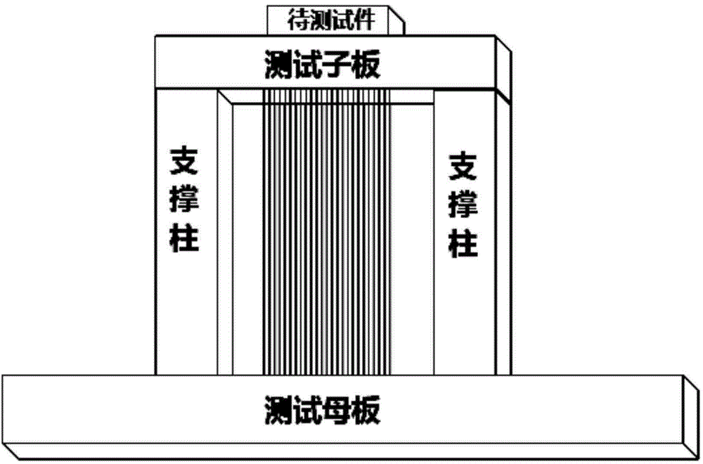
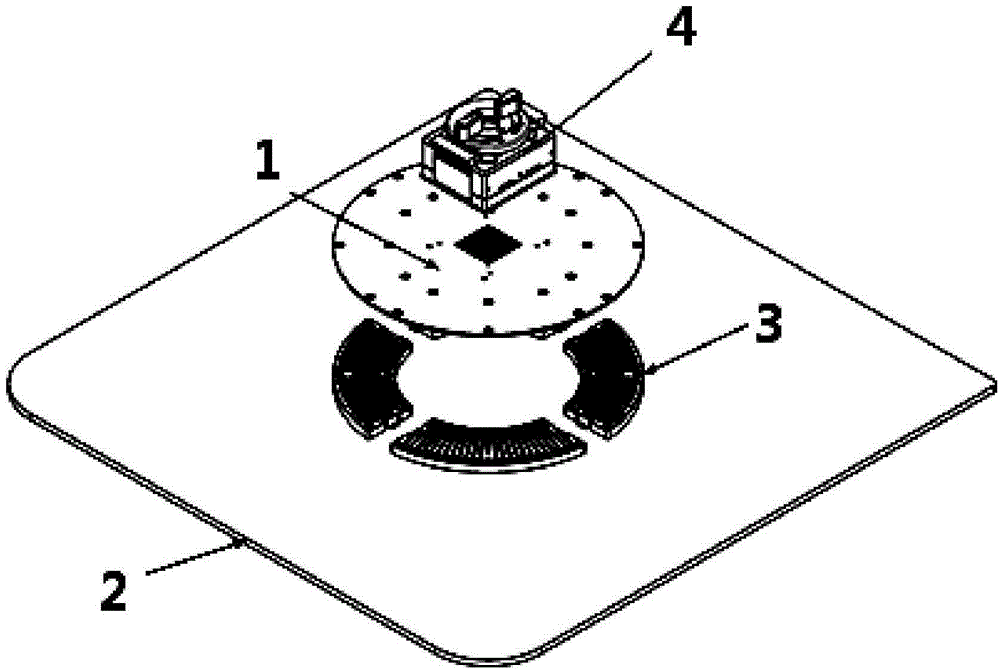
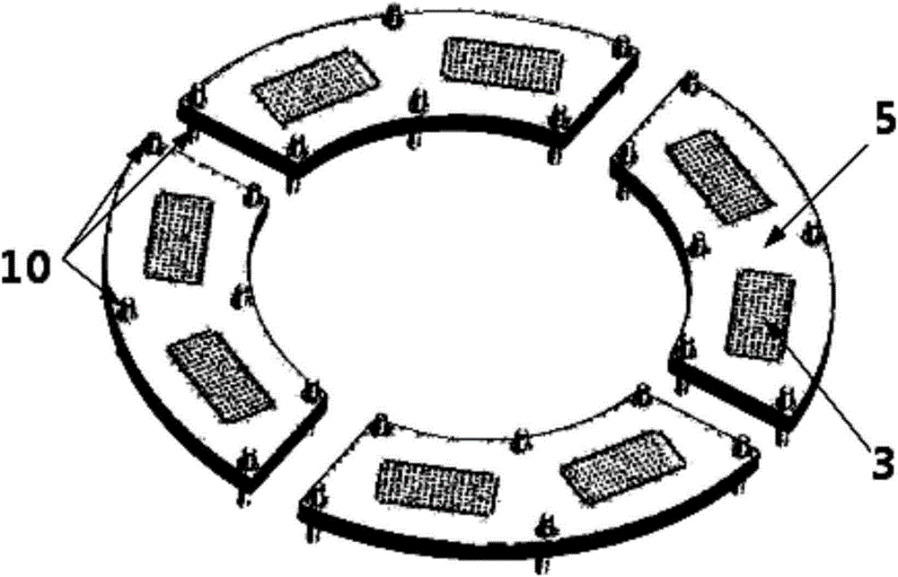
[0038] Such as figure 2 As shown, the test system of the present invention carries out structural and electrical connections by pressing and screwing the device to be tested, the test socket 4, the test sub-board 1, the pogo pin connector array 3, and the test motherboard 2, and finally passes the test system Docking with the motherboard to complete the power supply and the interaction test between the signal and the device under test. The entire pogo pin connector array is divided into 4 rectangular modules according to 90° sector and can be disassembled. The final forming structure of the pogo pin connector array is as follows image 3 shown. For each pogo pin connector, the specific structure is decomposed as follows: First, fix the stud on the metal base 5, and pass the stud directly through the stud mounting hole 6 on the metal base 5, and the raised ...


PUM


Abstract

Provided is a high-speed test system and processing method thereof for an ATE machine. The test system comprises a test daughter board and a test mother board. The test mother board is provided with a spring needle connector array, and the test daughter board is provided with a test socket. The test daughter board, the spring needle connector array and the test mother board are connected through a pressing screw connection mode. The processing method is characterized by, to begin with, pressing spring needles to a spring needle connector module; then, installing the spring needle connector module to a step-shaped groove reserved in a metal base through a screw connection mode; and finally, installing a stud running through the whole height of the test system to the metal base, wherein the two ends of the stud are screwed with the test daughter board and the test mother board respectively and independently, and thus pressing assembling work of the test system is finished. The high-speed test system and processing method not only can ensure repeated use and maintenance of the test system, but also can realize high-precision control of signal link impedance, and thus integrity of high-speed signal of the test system is guaranteed.

Description

technical field [0001] The invention belongs to the field of integrated circuit testing, and in particular relates to a high-speed testing system for ATE machines and a processing method thereof. Background technique [0002] Automatic test equipment (ATE) refers to a new type of test equipment that automatically completes signal measurement, data processing, transmission and display under the scheduling of test programs. The equipment plays the role of mass automated testing and screening in the development and mass production of integrated circuits. The daughter-mother board connection design generally adopted in the existing ATE test system has certain limitations. [0003] Such as figure 1 As shown, firstly, the device under test needs to be connected to the resources of the ATE machine through the socket, the daughter board, the welding cable, and the mother board. , not only seriously affects the assembly and welding cycle of the test system, but also causes serious...

Claims


Application Information

Patent Timeline
Patent Type & Authority Applications(China)
IPC IPC(8): G01R31/00
Inventor 张冰
Owner NO 771 INST OF NO 9 RES INST CHINA AEROSPACE SCI & TECH
Why Eureka
Try Eureka