Flue gas treatment device and method

A technology for flue gas treatment and flue gas, which is applied in the integrated device of nitrogen oxides, mercury and dust, and the field of sulfur dioxide. It can solve the problems that the dust removal effect cannot meet the requirements of the new standard, the denitrification and mercury removal efficiency is low, and the oxidation performance is poor. , to achieve the effects of saving ozone consumption, reducing water in flue gas, and low production cost

Inactive Publication Date: 2015-09-30
ZHONGJING ENVIRONMENTAL TECH CO LTD
View PDF22 Cites 4 Cited by
  • Summary
  • Abstract
  • Description
  • Claims
  • Application Information

AI Technical Summary

Problems solved by technology

Its dust removal method adopts wet dust removal, which not only has high power consumption and high resistance, but also the dust removal effect is far from meeting the requirements of the new standard, especially for PM2. Poor performance, low denitrification and mercury removal efficiency

Method used


Image

  • Flue gas treatment device and method
  • Flue gas treatment device and method
  • Flue gas treatment device and method

Examples


Embodiment approach

[0106] The flue gas oxidation step of the present invention is to use ozone and hydrogen peroxide to synergistically oxidize low-valent nitrogen oxides and elemental mercury in the flue gas in the ozone spray oxidation reaction layer and hydrogen peroxide spray oxidation reaction layer, and form high-valent nitrogen oxides substances and mercury oxide. Preferably, the flue gas oxidation step of the present invention includes: in the ozone spray oxidation reaction layer, spray ozone downward through the ozone atomization spray part; in the hydrogen peroxide spray oxidation reaction layer, spray The shower unit sprays hydrogen peroxide downwards. The atomization and spraying process used in the flue gas oxidation step is not particularly limited, and those well known in the art can be used. According to one embodiment of the present invention, the flue gas oxidation step preferably uses stainless steel nozzles to spray ozone and hydrogen peroxide. The synergistic oxidation pri...

Embodiment 1

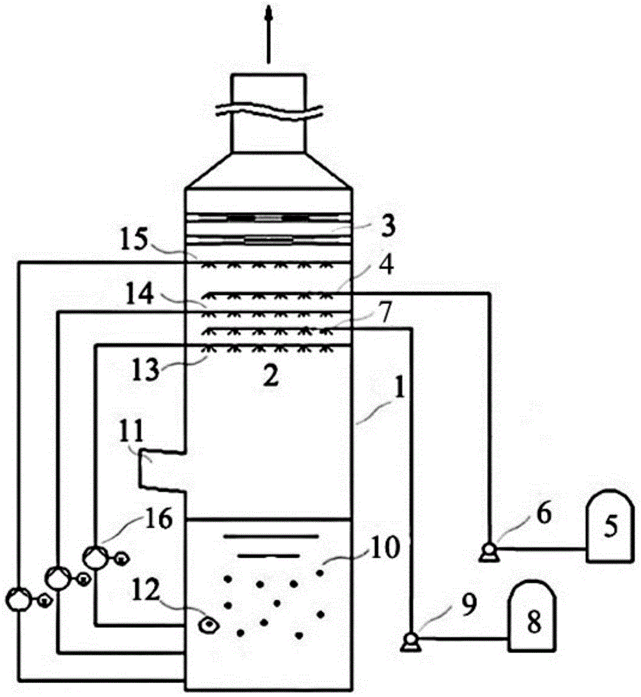
[0123] figure 1 A schematic diagram of the device of Example 1 of the present invention is shown. It can be seen from the figure that the flue gas treatment device of the present invention includes flue gas treatment equipment 1 , ozone supply equipment 5 , and hydrogen peroxide supply equipment 8 . The flue gas treatment equipment 1 includes an ozone spray oxidation reaction layer 4, a hydrogen peroxide spray oxidation reaction layer 7, an absorption spray area 2 and a slurry storage area 10, wherein the ozone spray oxidation reaction layer 4 and the hydrogen peroxide spray oxidation reaction layer 7 They are all located in the absorption spray area 2. The absorption spray zone 2 comprises a first absorption spray layer 13 , a second absorption spray layer 14 and a third absorption spray layer 15 . The hydrogen peroxide spray oxidation reaction layer 7 is located between the first absorption spray layer 13 and the second absorption spray layer 14 . The ozone spray oxidatio...

Embodiment 2

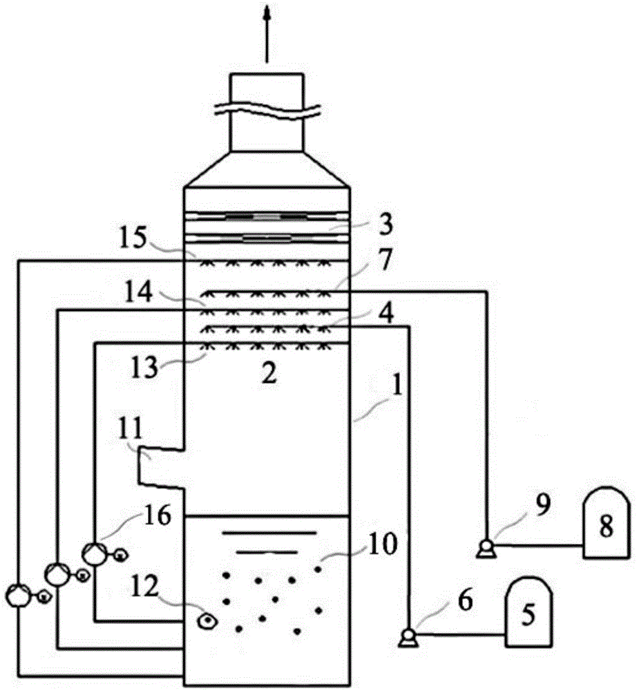
[0138] figure 2 A schematic diagram of the device of Example 2 of the present invention is shown. It can be seen from the figure that the flue gas treatment device of the present invention includes flue gas treatment equipment 1 , ozone supply equipment 5 , and hydrogen peroxide supply equipment 8 . The flue gas treatment equipment 1 includes an ozone spray oxidation reaction layer 4, a hydrogen peroxide spray oxidation reaction layer 7, an absorption spray area 2 and a slurry storage area 10, wherein the ozone spray oxidation reaction layer 4 and the hydrogen peroxide spray oxidation reaction layer 7 They are all located in the absorption spray area 2. The absorption spray zone 2 comprises a first absorption spray layer 13 , a second absorption spray layer 14 and a third absorption spray layer 15 . The ozone spray oxidation reaction layer 4 is located between the first absorption spray layer 13 and the second absorption spray layer 14 . The hydrogen peroxide spray oxidati...


PUM


Abstract

The invention discloses a flue gas treatment device and method, namely an integrated flue gas desulfurization, denitrification, demercuration, dedusting and defogging device and method. The device comprises flue gas treatment equipment, ozone supply equipment, hydrogen peroxide supply equipment and the like, wherein the flue gas treatment equipment comprises an ozone spray oxidation reaction layer, a hydrogen peroxide spray oxidation reaction layer, an absorbing sprinkling area, a slurry storage area and a dedusting and defogging area; both the ozone spray oxidation reaction layer and the hydrogen peroxide spray oxidation reaction layer are arranged in the absorbing sprinkling area; the dedusting and defogging area is positioned above the absorbing sprinkling area. The device and the method provided by the invention are suitable for integrated desulfurization, denitrification, demercuration, dedusting and defogging treatment of flue gas which contains SO2, NOX, Hg<0> and dust, and is produced by coal burning boilers, steel sintering machines, pellets, industrial furnaces and the like, and can solve the problem that a conventional process is complex in equipment, high in running cost and energy consumption, and low in demercuration and denitration efficiencies.

Description

technical field [0001] The invention relates to a flue gas treatment device and method, in particular to an integrated device and method for simultaneously removing sulfur dioxide, nitrogen oxides, mercury and dust in the flue gas. Background technique [0002] Industrial flue gas contains a large amount of dust, sulfur dioxide (SO 2 ), nitrogen oxides (NO X ) and other harmful substances, which are the main precursors and important sources of acid rain and smog. Elemental mercury (Hg 0 ) is the only toxic heavy metal that is gaseous at normal temperature and pressure. It has the ability to diffuse over long distances and is a global pollutant. Although the mercury content in industrial flue gas is very low, its harm to the environment cannot be ignored due to the large amount of flue gas. Therefore, the control of SO in industrial flue gas 2 , NO X , mercury and dust emissions are the most important tasks in the field of air pollution control. [0003] If the above-m...

Claims


Application Information

Patent Timeline
IPC IPC(8): B01D53/76B01D53/80B01D53/60B01D53/64B01D50/00
CPCY02A50/20
Inventor 童裳慧
Owner ZHONGJING ENVIRONMENTAL TECH CO LTD
Why Eureka
Try Eureka