
Semi-physical simulation method of inertially stabilized platform control system

An inertial stable platform, semi-physical simulation technology, applied in general control systems, control/regulation systems, instruments, etc., can solve problems such as evaluation, development cycle is too long, and the ideal simulation effect cannot be achieved.

Active Publication Date: 2015-09-30
EMERCYS ELECTRONICS
View PDF4 Cites 12 Cited by
  • Summary
  • Abstract
  • Description
  • Claims
  • Application Information

AI Technical Summary

Problems solved by technology

[0003] A high-confidence, convenient and economical simulation method is of great significance to the design of a stable platform control system. In traditional control theory research, Matlab / Simulink can be used to conveniently design and simulate control laws, but most of the current Simulink simulations are non- Real-time simulation, that is, pure mathematical modeling and simulation, the hardware link in the control system is replaced by a mathematical model, which often fails to achieve the expected ideal simulation effect
However, physical experiments cannot evaluate real-time parameters such as memory, interface, and communication, so designers must constantly make adjustments to their own designs, and the development cycle is relatively long

Method used


Image

  • Semi-physical simulation method of inertially stabilized platform control system
  • Semi-physical simulation method of inertially stabilized platform control system
  • Semi-physical simulation method of inertially stabilized platform control system

Examples


Embodiment Construction

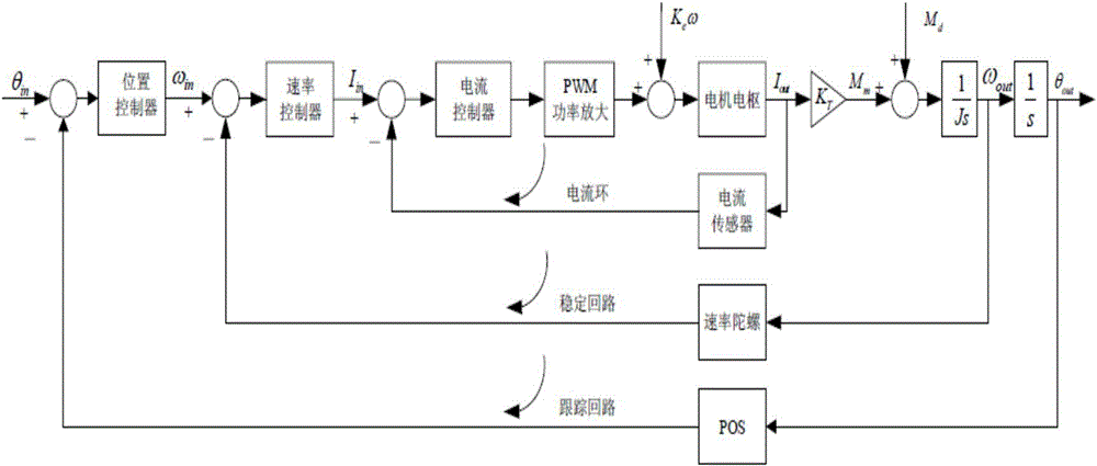
[0021] The control structure of the three axes of the inertial stable platform is basically the same, so the mathematical model of the control system of the single axis inertial stable platform is established first. The working principle of the single-axis inertial stabilized platform control system is as follows: figure 1 shown.

[0022] The inertial stable platform belongs to the motion servo system of mechatronics. The whole control system is a three-closed-loop control system consisting of a current loop, a velocity loop (stabilizing loop) and a position loop (tracking loop). The actuator of the control system is a DC torque motor, the controlled object is a stable platform body, the rate gyroscope is an angular rate sensor, and the POS or accelerometer is a position sensor. The working principle of the control system is that the servo controller generates a control signal to the torque motor based on the angular rate information of the frame sensitive to the rate gyro an...


PUM


Abstract

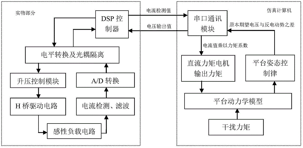
The invention provides a semi-physical simulation method of an inertially stabilized platform control system. Pure mathematics simulation is real difficultly in the design of the inertially stabilized platform control system, the cost of real object experiments is high, and models are difficult to change. A digital model portion and a real object portion are used in the method, wherein the digital model portion is used for modeling detection feedback links of a kinetic model, a posture control law, revolving speed and an angular position of a stabilized platform and converting the detection feedback links into real-time procedures; a current value measured by the real object portion is corrected into output torque of an executing mechanism; the output torque is substituted into a digital model to obtain an armature voltage expected value of the next moment; the armature voltage expected value is transmitted to a hardware portion; and the real object portion comprises a controller, a driving circuit and a current detecting circuit. The problem that a real effect is difficult to achieve when mathematical simulation is carried out by the real object portion is solved. The semi-physical simulation method of the inertially stabilized platform control system has advantages of high instantaneity of the real object experiments, high degree of confidence and convenience, flexibility and economy in mathematical simulation. A design period of the inertially stabilized platform control system can be shortened, and the cost is reduced.

Description

technical field [0001] The invention relates to a semi-physical simulation method of an inertial stable platform control system, which is used to overcome the shortcomings of the mathematical simulation in the design process of the inertial stable platform control system that is difficult to achieve the desired effect, high cost and long cycle of physical experiments, and is suitable for reducing inertia Stabilize the design cost of the platform control system and shorten the development cycle. Background technique [0002] High-resolution earth observation systems are widely used in military reconnaissance, basic surveying and mapping, disaster monitoring and other fields. In order to realize the ideal observation of the earth, it is required that the camera load can be kept stable. However, due to the influence of factors such as atmospheric turbulence and self-disturbance, it is difficult for the camera load to maintain an ideal stable state, which makes the visual axis u...

Claims


Application Information

Patent Timeline
IPC IPC(8): G05B17/02
Inventor 李明陈明辰张延顺
Owner EMERCYS ELECTRONICS
Learn More