A Two-Stage Preheating Air Boiler Using Full Backfiring Finned Water Tube Grate

A technology for preheating air and fins, which is applied to the grate, water heater, and grate of hollow grate bars, which can solve the problems of environmental pollution, potential safety hazards, waste of energy, etc., so as to improve the utilization rate and increase the burning speed. and combustion temperature, the effect of reducing wear

Active Publication Date: 2018-04-03
SHANXI XINJUXING BOILER
View PDF6 Cites 0 Cited by
  • Summary
  • Abstract
  • Description
  • Claims
  • Application Information

AI Technical Summary

Problems solved by technology

[0004] In order to solve the problems of wasting energy, polluting the environment and potential safety hazards existing in the existing counter-firing boilers, the present invention further provides a two-stage preheating air boiler using a fully counter-firing finned water tube grate

Method used


Image

  • A Two-Stage Preheating Air Boiler Using Full Backfiring Finned Water Tube Grate
  • A Two-Stage Preheating Air Boiler Using Full Backfiring Finned Water Tube Grate
  • A Two-Stage Preheating Air Boiler Using Full Backfiring Finned Water Tube Grate

Examples


Embodiment 1

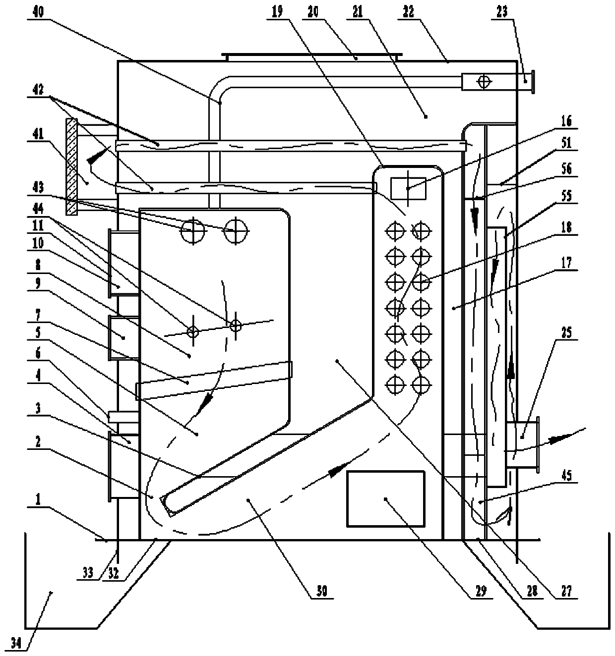
[0040] Such as figure 1 , 2 , A kind of two-stage preheating air boiler using the full back-fired finned water tube grate shown in 3 and 4 includes a furnace body made of an inner tank 19 and an outer shell 22 and a base 1 supporting the furnace body. The interior of the furnace body is divided into a feeding chamber 8, a combustion chamber 5, a heat-absorbing area 30 and an air preheating chamber, which are successively connected by the smoke-blocking return device 3, the back-burning finned water tube grate 7, the smoke-blocking return plate 17 and the furnace return plate 27. In the heat zone, a number of heat-absorbing pipes 18 are installed in the heat-absorbing zone 30 , and a fire outlet 2 is provided at the bottom of the combustion chamber 5 . The charging chamber 8 and the combustion chamber 5 are separated by the back-burning finned water tube fire grate 7, the feeding chamber 8 is located above the combustion chamber 5, and the heat-absorbing zone 30 and the air pr...

Embodiment 2

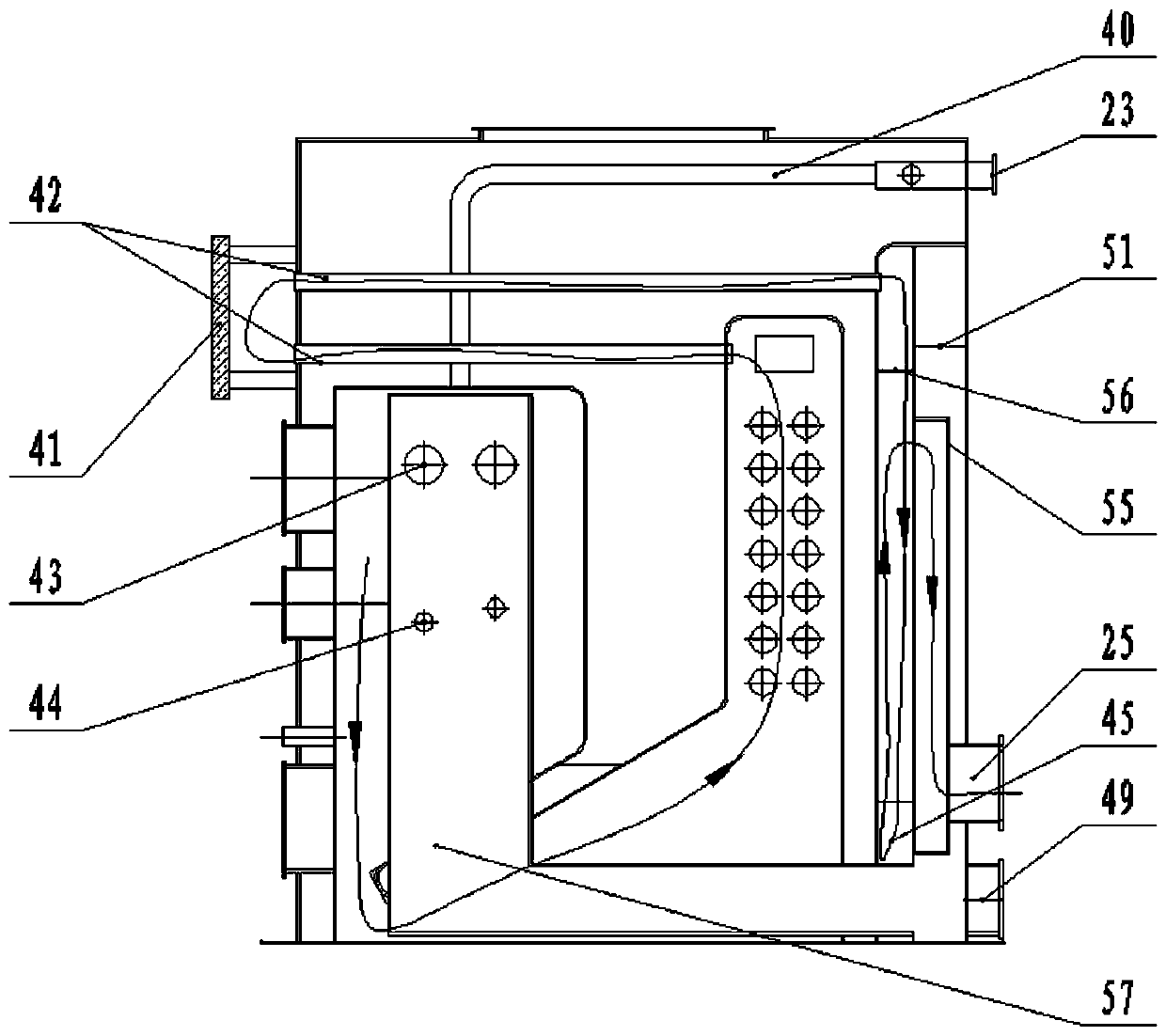
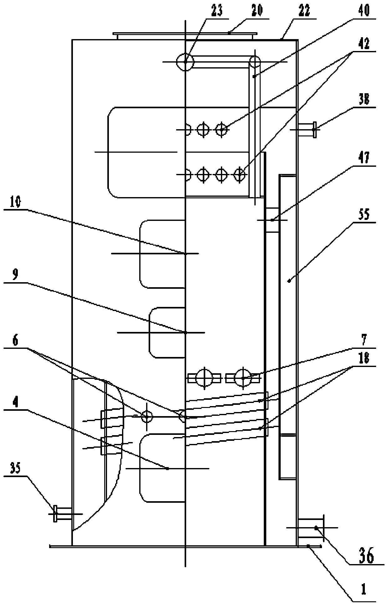
[0057] Such as Figure 5 , 6 In the schematic diagram of the boiler structure of Scheme 2 shown, there are also a number of ash and flue gas vents 14 that pass through the feeding chamber 8 and the heat absorption area 30 on the upper part of the furnace return plate 27, and the ash and flue gas vents 14 are An adjustment plate 15 is provided. When stopping the furnace or sealing the fire, open the regulating plate 15 on the ash and flue gas vent 14, open the regulating valve at the flue gas vent 23 at the same time, and close the valve of the primary damper 12, and open the secondary regulating valve of the combustion chamber. Damper 6 allows residual air to be discharged to realize safe operation.

[0058] It can be seen from this that the structural difference between Scheme 2 (Example 2) and Scheme 1 (Example 1) lies in:

[0059] 1. The liner in Scheme 1 is a special-shaped structure, that is, the smoke-shielding return plate 17 and the furnace return plate 27 are direc...


PUM


Abstract

The invention belongs to the technical field of fire coal, coke and biomass fuel boilers, and provides a two-stage preheating wind boiler using an all-reversal-combustion fin type water tube grate. The problems that energy waste, environment pollution and potential safety hazards are caused by an existing reversal-combustion boiler are solved. The all-reversal-combustion fin type water tube grate is adopted by the boiler, the fire outlet sectional area of the grate is greatly enlarged on the basis of the same grate area, and the combustion speed and combustion temperature are increased; a preheating area and a triple valve structure are adopted, hot air preheated by the air preheating area can be fed into a hearth through a preheating air inlet, the temperature of the furnace is raised, the contact area between hot oxygen and fuel is greatly enlarged, it can be ensured that smoke is fully combusted through multiple times of wind combustion supporting, the fuel utilization rate is increased, the smoke emission temperature is lowered, exhausted smoke does not contain CO, clean combustion is achieved, and meanwhile the potential safety hazards of toxic gas in smoke are eliminated.

Description

technical field [0001] The invention belongs to the technical field of coal-burning, coke and biomass fuel boilers, and in particular relates to a two-stage preheating air boiler using a full reverse-firing finned water tube grate. Background technique [0002] When the existing reverse combustion boiler is burning, because the cross-sectional area of ​​the fire outlet is small, the fire outlet is not smooth, the smoke resistance is large, and the furnace temperature is low, resulting in a low burnout rate of the fuel and a waste of energy. Moreover, the flue gas after combustion contains a certain proportion of CO and a large number of ash particles, which is not environmentally friendly, but also affects the compliance of desulfurization and dust removal equipment in the subsequent sequence and the service life of the fan, especially in workshops with poor ventilation. The accumulation of leaks will cause staff poisoning, which poses a serious safety hazard. [0003] From...

Claims


Application Information

Patent Timeline
Patent Type & Authority Patents(China)
IPC IPC(8): F23B30/02F23H3/02F23L9/00F23L15/00F23J3/00F24H1/40
CPCY02E20/34
Inventor 任二平
Owner SHANXI XINJUXING BOILER
Why Eureka
Try Eureka