
Garbage leachate treatment process and system

A technology for landfill leachate and treatment process, which is applied in the field of wastewater treatment and can solve the problems of reduced evaporation efficiency, slower flow speed, and inability to perform cleaning.

Pending Publication Date: 2015-10-28
GUANGZHOU SCHIN TECH IND CO LTD
View PDF3 Cites 6 Cited by
  • Summary
  • Abstract
  • Description
  • Claims
  • Application Information

AI Technical Summary

Problems solved by technology

[0004] 1. The circular tube is easy to cause the phenomenon of liquid film bias;
[0005] 2. When the evaporation concentration is too high, the flow speed will slow down, reducing the heat transfer coefficient and reducing the evaporation efficiency;
[0006] 3. The accumulation of condensed water generated during the heat exchange process in the heat exchange tube will occupy a large part of the heat exchange area, which will reduce the evaporation efficiency;
[0007] 4. The concentrated solution is easy to scale on the pipe wall, and because of the shell side, it cannot be cleaned;
[0008] 5. Need fresh steam as heat source, high energy consumption
[0011] Secondly, it is easy to drift, resulting in uneven distribution of liquid and reducing the effective heat transfer area;
[0012] Again, a layer of viscous organic dirt will be formed outside the horizontal tube and adhere to the horizontal tube, which will also greatly reduce the heat transfer coefficient of the horizontal tube

Method used


Image

  • Garbage leachate treatment process and system
  • Garbage leachate treatment process and system
  • Garbage leachate treatment process and system

Examples


Embodiment Construction

[0104] The present invention will be described in detail below in conjunction with the accompanying drawings and specific embodiments, where the schematic embodiments and descriptions of the present invention are used to explain the present invention, but not to limit the present invention.

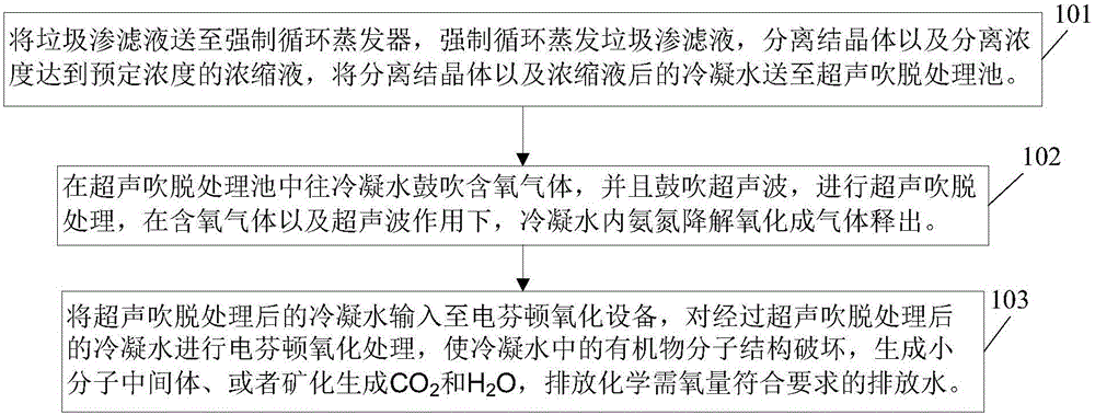
[0105] see figure 1 As shown, this embodiment provides a process suitable for landfill leachate treatment, which mainly includes:

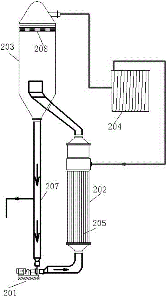
[0106] Step 101: Send the landfill leachate to the forced circulation evaporator, force the circulation to evaporate the landfill leachate, separate the crystals and the concentrated solution whose concentration reaches a predetermined concentration, and send the condensed water after the separated crystals and the concentrated solution to the ultrasonic stripping treatment pool .

[0107] As an illustration of this embodiment, this embodiment can be realized by using, but not limited to, any forced circulation evaporator in the prior art and an existing for...


PUM


Abstract

A garbage leachate treatment process and system are provided. The process includes the steps: sending a garbage leachate to a forced circulation evaporator, carrying out forced circulation evaporation of the garbage leachate, separating a crystal and separating a concentrated solution with the concentration reaching a preset concentration; sending condensed water discharged after the crystal and the concentrated solution of the garbage leachate are treated and separated in the step 1 to an ultrasonic blowoff treatment tank, blowing oxygen-containing gas to the condensed water, blowing ultrasonic waves, carrying out ultrasonic blowoff treatment, under the action of the oxygen-containing gas and the ultrasonic waves, allowing ammonia nitrogen in the condensed water to be degraded and oxidized into gas, and releasing; and inputting the condensed water after ultrasonic blowoff treatment to an electro-fenton oxidation device, carrying out electro-fenton oxidation treatment on the condensed water, destroying molecular structures of organic matters in the condensed water, generating small molecule intermediates, or mineralizing to form CO2 and H2O, and discharging discharged water having the chemical oxygen demand meeting requirements. The method has the advantages of energy-saving and environmental-protection application, and high processing efficiency.

Description

technical field [0001] The invention relates to the field of waste water treatment, in particular to a landfill leachate treatment process and system. Background technique [0002] Domestic waste leachate mainly comes from the moisture contained in the garbage itself in the domestic waste landfill, the rain and snow water entering the landfill and other moisture. Landfill leachate is a kind of high-concentration organic wastewater with high salt content, high concentration of organic matter, ammonia nitrogen (referring to free ammonia (or non-ion ammonia, NH 3 ) or ionic ammonia (NH 4 +) Nitrogen in form) is also denoted as NH 3 -N) high concentration, unbalanced microbial nutrient ratio, heavy metal content, large water quality fluctuations, and difficult treatment. How to properly treat it so that it can meet the discharge standards has always been a major problem in the field of environmental protection at home and abroad. Traditional treatment methods can be divided i...

Claims


Application Information

Patent Timeline
IPC IPC(8): C02F9/10C02F101/16
Inventor 何汉锋林火灿李健生毕永锐姜广义舒俭
Owner GUANGZHOU SCHIN TECH IND CO LTD
Learn More