
Random laser, random resonant cavity manufacture method and small particle concentration detection method

A random laser and random laser technology, applied in the laser field, can solve the problems of poor output laser controllability, long gain length, gain discontinuity, etc., and achieve controllable output, good gain effect, and reduced gain length.

Active Publication Date: 2015-10-28
UNIV OF ELECTRONIC SCI & TECH OF CHINA
View PDF6 Cites 15 Cited by
  • Summary
  • Abstract
  • Description
  • Claims
  • Application Information

AI Technical Summary

Problems solved by technology

[0003] In order to overcome the technical defects that the existing random laser requires a long gain length and high pump power to lase, and the gain is discontinuous, and the controllability of the output laser is poor, the invention provides a random laser and a random resonator in the random laser Manufacturing method and detection method for detecting the concentration of tiny particles using a random laser

Method used


Image

  • Random laser, random resonant cavity manufacture method and small particle concentration detection method
  • Random laser, random resonant cavity manufacture method and small particle concentration detection method
  • Random laser, random resonant cavity manufacture method and small particle concentration detection method

Examples


specific Embodiment approach

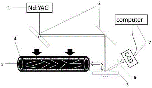
[0045] The invention discloses a random laser, which includes:

[0046] Pumping light source 1, used to generate pumping light waves;

[0047] Laser reflector 2, used to reflect the pump light wave;

[0048] The capillary 3 is used to receive the pump light wave reflected by the laser mirror 2, provide the pump light wave gain and excite the random laser;

[0049] Dye solution 5, used to act as a gain medium;

[0050] Optical filter 6, used to filter the pumping light wave;

[0051] The inner wall of the capillary 3 is coated with a layer of random dielectric film 4 mixed with nano-TiO2 particles and ultraviolet glue, and the dye solution 5 is filled inside the capillary 3 to form a random resonant cavity;

[0052] The pumping light wave generated by the pumping light source 1 is reflected by the laser reflector 2 and irradiates the random resonator to excite the random laser, which is filtered by the filter 6 after outputting the random laser.

[0053] Random laser is a r...

Embodiment 1

[0083] Such as figure 1 The shown random laser uses a pump light source 1 with a wavelength of 532 nm, a laser mirror 2 and an optical filter 6, the dye solution 5 uses an aqueous solution of rhodamine 6G, and the capillary 3 uses a 1017Q capillary with an inner diameter of 100 um and an outer diameter of The thickness is 170um, and the random dielectric film 4 is a mixture of nano TiO2 particles and ultraviolet glue.

[0084] First, the effect of TiO2 particles is verified by two experiments:

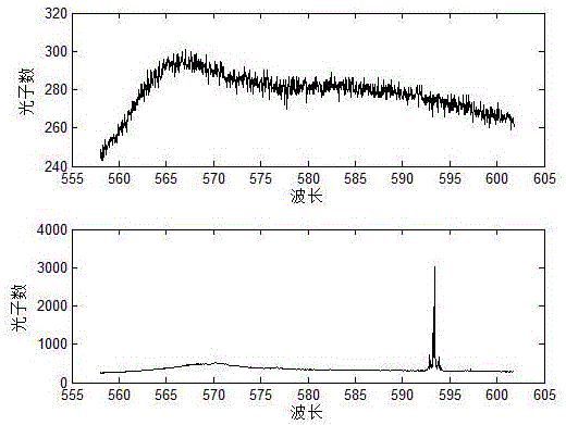
[0085] The first one: only a thin layer of ultraviolet glue is coated on the inner wall of the capillary, cured by ultraviolet light irradiation, and filled with the dye solution at a constant speed through the control of a micro-injection pump. The dye solution is an aqueous solution of rhodamine 6G, wherein the filling matrix is ​​deionized water, the gain medium is rhodamine 6G, and the concentration of the rhodamine solution is 1mol / L. exist figure 1 The spectrogram is observed ...


PUM


Abstract

The present invention discloses a random laser which comprises a pump light source, a laser reflection lens, a capillary, a dye solution, and a light filter. The inner wall of the capillary is coated with a layer of random medium film formed by mixing nano TiO2 particles and an ultraviolet glue. The capillary is filled by the dye solution to form a random resonant cavity. The pump light wave generated by the pump light source is reflected by the laser reflection lens to irradiate the random resonant cavity, random laser is excited, and the random laser is outputted and filtered by the light filter. The invention also discloses a random resonant cavity manufacture method and a small particle concentration detection method. According to the random laser, the inner wall of the random laser resonant cavity is coated by the random medium film formed by mixing the nano TiO2 particles and the ultraviolet glue, under the effect of multiple scattering, the retention time of the light in a gain medium is increased, the gain length is reduced, the amplification of the light is enhanced, a gain is larger than a loss, the pumping power is reduced, and the controllable output of the random laser is realized.

Description

technical field [0001] The invention relates to a random laser, which belongs to the field of lasers, and more specifically relates to a random laser, a method for manufacturing a random resonant cavity in the random laser, and a method for detecting the concentration of tiny particles by using the random laser. Background technique [0002] Since Letokhov theoretically predicted the existence of random lasers (RLS), RLS has attracted increasing attention due to its unique properties. In contrast to conventional lasers, which require cavities formed by fixed mirrors, RLS relies only on active and scattering media, where optical feedback is achieved by multiple light scattering. Light undergoes multiple scattering before escaping from the gain medium. Multiple scattering increases the residence time of light in the gain medium (that is, increases the distance traveled by light in the gain medium), and enhances the amplification of light. In this case, it is no longer necess...

Claims


Application Information

Patent Timeline
IPC IPC(8): H01S3/08H01S3/10G01N15/06
Inventor 张伟利郑梦雅马瑞饶云江宋云波
Owner UNIV OF ELECTRONIC SCI & TECH OF CHINA
Features
  • Generate Ideas
  • Intellectual Property
  • Life Sciences
  • Materials
  • Tech Scout
  • Unparalleled Data Quality
  • Higher Quality Content
  • 60% Fewer Hallucinations
Learn More