Synchronous rectification control method, control device and switch power supply

A synchronous rectification and control device technology, applied in control/regulation systems, output power conversion devices, electrical components, etc., can solve the problems of low light load efficiency, large no-load loss, large output current, etc., and achieve high full load efficiency , small no-load power consumption and simple circuit

Active Publication Date: 2015-10-28
MORNSUN GUANGZHOU SCI & TECH
View PDF4 Cites 23 Cited by
  • Summary
  • Abstract
  • Description
  • Claims
  • Application Information

AI Technical Summary

Problems solved by technology

Although the current-type synchronous rectification overcomes the problems of large no-load loss and low light-load efficiency, it is also not suitable for high-power-density module power supplies, because the current-driven synchronous rectification uses transformers and resistors that are connected in series with the switching power supply. On the main power circuit on the side, the output current of the high power density power supply is generally very large, which will cause a lot of loss at full load and reduce the full load efficiency of the high power module power supply
For example, when a 3.3V output 100W power supply is working at full load, the output current reaches 30A. If a resistance of 5mΩ is used, it will cause a loss of nearly 5W, and the efficiency will drop by more than 4%.
Therefore, the use of this driving scheme reduces the full-load efficiency when the light-load efficiency is improved, and the gain outweighs the gain.
The increase in volume caused by the use of resistance or current transformers is also unacceptable for high power density power supplies

Method used


Image

  • Synchronous rectification control method, control device and switch power supply
  • Synchronous rectification control method, control device and switch power supply
  • Synchronous rectification control method, control device and switch power supply

Examples


Embodiment 1

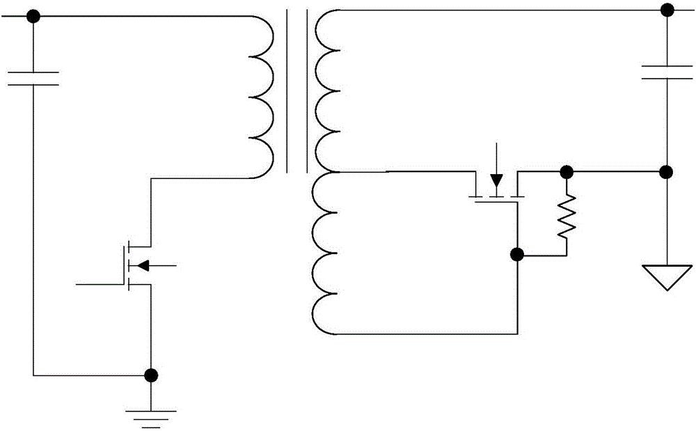
[0057] Figure 6 A synchronous rectification drive control circuit according to Embodiment 1 of the present invention is shown. A synchronous rectification control circuit includes a winding self-driven synchronous rectification circuit 2 , an auxiliary power supply circuit 3 and a drive control circuit 4 .

[0058] Wherein, the driving control circuit 4 receives the induced voltage of the auxiliary power supply circuit 3, and forms a control signal according to the level of the induced voltage of the auxiliary power supply circuit 3, and when the level of the auxiliary power supply circuit 3 is low, the control signal will drive the winding synchronously The drive of the rectifier circuit 2 is turned off, and when the level of the auxiliary power supply circuit 3 is high, the control signal does not interfere with the winding to self-drive the synchronous rectifier circuit 2 .

[0059] After the winding self-driven synchronous rectification circuit 2 is turned off by the cont...

Embodiment 2

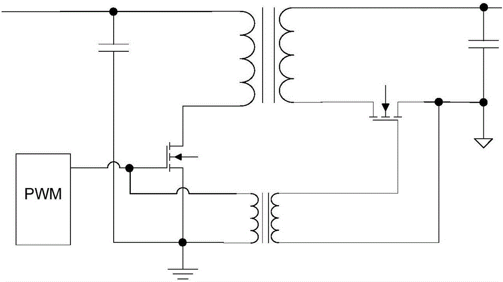
[0067] Figure 8 It shows the synchronous rectification drive control circuit of the second embodiment of the present invention.

[0068] A synchronous rectification control circuit, comprising a power conversion circuit 1, a winding self-driven synchronous rectification circuit 2, an auxiliary power supply circuit 3, and a drive control circuit 4. The difference from the first embodiment is that the control IC in the drive control circuit 4 is not an operational amplifier, but a TL431.

[0069] Preferably, the drive rectification control circuit 4 includes a first sampling resistor R41, a second sampling resistor R42, a first output pull-up resistor R43, a first error amplifier IC U41, a first current limiting resistor R44, and a second current limiting resistor R45 , the first switching transistor Q41 and the first diode D41.

[0070] Preferably, one end of the first sampling resistor R41 is connected to the output VCC end of the auxiliary power supply circuit 3 . The oth...


PUM


Abstract

The invention relates to synchronous rectification control method which is used for carrying out synchronous rectification control on a synchronous rectification MOS tube of a switch power supply. A power converter, a winding self-driven synchronous rectification circuit, a synchronous rectification control circuit and a secondary side VCC circuit are comprised. The method is characterized in that the synchronous rectification control circuit detects output voltage change of a secondary side VCC winding and outputs a control signal; usually, when the output load of the switch power supply is empty or light, the output voltage of the secondary side VCC winding is lower than the output voltage in the case of full load or heavy load; the control signal switches off the drive of the winding self-driven synchronous rectification circuit in the case of empty load or light load; the synchronous rectification tube works in a body-diode rectification work state; current zero-crossing is prevented; and power consumption is small in the case of empty load or light load.

Description

technical field [0001] The present invention relates to a switching power supply, in particular to a synchronous rectification control method, a control device and a switching power supply based on the control device, so as to be suitable for switching power supplies with high input voltage, small power supply volume, and low no-load or light-load power consumption application field. Background technique [0002] With the rapid development of semiconductor devices and VLSI, the demand for high-current, low-voltage, and low-cost isolated switching power supplies has also increased significantly. The Schottky diode with a forward voltage drop of only 0.3V-0.7V rectifies, and the large conduction loss becomes the bottleneck of the miniaturization of the switching power supply. In order to improve the efficiency of low-voltage, high-current switching power supplies, synchronous rectification technology is used for output rectification. In the prior art, three driving methods ar...

Claims


Application Information

Patent Timeline
Patent Type & Authority Applications(China)
IPC IPC(8): H02M3/335
CPCY02B70/10
Inventor 李绍兵
Owner MORNSUN GUANGZHOU SCI & TECH
Why Eureka
Try Eureka