Oil extraction method utilizing circulated heating cavity gases

A gas circulation and cavity technology, which is applied in the development of fluids, earthwork drilling, wellbore/well components, etc., can solve the problems of high cost of polluted wastewater treatment, large boiler space, and difficult technical implementation, etc. Effective production period, reduced processing costs, and the effect of reducing oil production costs

Inactive Publication Date: 2015-11-04
石晓岩
View PDF6 Cites 2 Cited by
  • Summary
  • Abstract
  • Description
  • Claims
  • Application Information

AI Technical Summary

Problems solved by technology

[0004] Looking at the existing thermal recovery technologies, the current heat supply is mostly steam as a thermal fluid, which has strict requirements on equipment, high energy consumption for steam generation, large boiler footprint, high heat loss, large well depth, limited space or load bearing And oil fields that are obviously affected by climatic conditions, the technical implementation is difficult
[0005] In addition, when oil wells or well groups are exploited using steam huff and puff or steam flooding, the production cost is high, water resources are seriously wasted, and the cost of polluted wastewater treatment is high.
High cost and high pollution limit the development of thermochemical oil recovery using steam as fluid

Method used


Image

  • Oil extraction method utilizing circulated heating cavity gases
  • Oil extraction method utilizing circulated heating cavity gases

Examples


Embodiment 1

[0033] The present invention can be applied to oil recovery of throughput type, and can also be applied to oil recovery of oil displacement type. For ease of description, this embodiment takes the oil flooding type as an example for illustration.

[0034] The collection well pipe and injection well pipe of cavity gas, the oil production well pipe and the flue gas injection well pipe can share one or several well pipes by using the casing, or use independent well pipes respectively. In this embodiment, an independent well pipe is taken as an example for illustration.

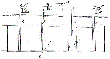
[0035] from figure 1 It can be seen from the figure that an oil recovery method using cavity gas circulation heating uses pressure difference to separate the cavity gas in the oil layer 30 through the separator 1 for gas-liquid separation, and then enters the heating device 11 through the pumping well pipe 2 . The pressure difference can be the difference between reservoir pressure and atmospheric pressure, or ...

Embodiment 2

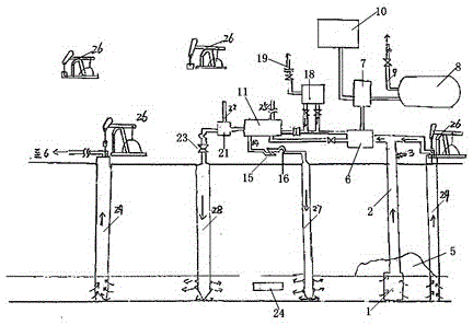
[0037] This embodiment also takes the oil flooding type as an example for illustration. refer to figure 2 , the cavity gas in the reservoir 4 enters the gas-liquid separator 6 through the pumping well pipe 2 by using the pressure difference. After the extraction, use the sampling device 3 to sample the cavity gas to grasp the oxygen content to ensure production safety. The above-mentioned pressure difference may be the difference between reservoir pressure and atmospheric pressure, or a pressure difference created by external force.

[0038] If the water content in the separated liquid is not high, it can directly enter the oil collector 8. If the water content in the separated liquid is high, it will first enter the oil-water separator 7 for oil-water separation, and the separated oil will enter the oil collector 8. The separated water can be concentrated to the water storage device 10, and the separated water can be injected into the downhole, or discharged after purifica...


PUM


Abstract

The invention provides an oil extraction method utilizing circulated heating cavity gases. The method includes heating oil layer cavity gas which enters into a heating device, and extracting oil after injecting heated cavity gases into an oil layer. In this method, flue gas generated by the heating device is injected into the oil layer, and some cavity gases enter into the heating device to serve as fuel for the heating device to form a circulated heating system. By utilizing the method, the oil extraction cost is low, no water resource is needed, contaminated water processing cost is reduced, the pressure and temperature are adjustable, the oil-gas ratio of oil extraction is high, and the yield is high.

Description

technical field [0001] The invention relates to the technical field of oil recovery, in particular to an oil recovery method utilizing cavity gas circulation heating. Background technique [0002] In the current land or offshore oil fields, many oil layers have high viscosity and high freezing point characteristics due to the large proportion of colloids, asphaltenes and long-chain paraffins, resulting in poor fluidity of crude oil in the reservoir and wellbore , especially a class of oil layers that reach the level of heavy oil, which is difficult to exploit and has a low recovery factor. Heavy oil refers to high-viscosity heavy crude oil with a viscosity greater than 50 mPa·s under formation conditions, or a degassed crude oil with a viscosity of 1000-10000 mPa·s at the reservoir temperature. Heavy oil has high viscosity, high density and less light distillates, so it is difficult to exploit. [0003] But at the same time, studies have found that this type of oil layer i...

Claims


Application Information

Patent Timeline
Patent Type & Authority Applications(China)
IPC IPC(8): E21B43/24E21B43/22E21B43/16
Inventor 石志宽石若溪焦润山石志聪石晓岩
Owner 石晓岩
Why Eureka
Try Eureka