Supercharge Your Innovation With Domain-Expert AI Agents!

A cupola waste heat utilization dust removal and desulfurization integrated system

A cupola and waste heat technology, applied in furnaces, waste heat treatment, furnace components, etc., can solve the problems of complex dust removal equipment, rising flue gas temperature, and large floor space, achieving good dust removal and desulfurization effect, prolonging service life, occupying Small area effect

Active Publication Date: 2017-06-16
青岛中智达环保熔炼设备有限公司
View PDF5 Cites 0 Cited by
  • Summary
  • Abstract
  • Description
  • Claims
  • Application Information

AI Technical Summary

Problems solved by technology

These substances are not only harmful to humans, but also have great harm to the natural environment, causing serious pollution to the atmosphere.
At present, in order to meet the emission standards stipulated by the state, the dust removal equipment is very complicated, occupies a large area, and requires a lot of investment.
[0003] The problems existing in the existing cupola dust removal technology are: 1. The flue gas temperature is high
When the cupola furnace is in normal furnace condition, the temperature of the flue gas is ≤120°C after mixing with the cold air from the feeding port; when the feeding is not timely, the temperature of the flue gas rises sharply in the empty furnace, shed material and the instant the furnace is opened, up to 600°C-800°C, which is Difficulties with a single dry dust removal method
2. There is a lot of dust, the proportion of fine powder is large, and most of them are not hydrophilic
If wet dust removal is used, the water is acidic, easy to corrode equipment, harmful to people, and pollutes water quality and soil
[0004] The flue gas discharged from the cupola has a very high temperature, which is generally discharged directly or after cooling treatment, and the waste heat of the flue gas is wasted

Method used


Image

  • A cupola waste heat utilization dust removal and desulfurization integrated system
  • A cupola waste heat utilization dust removal and desulfurization integrated system

Examples


Embodiment Construction

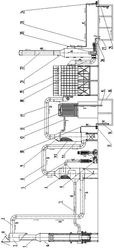
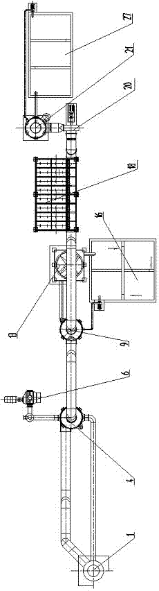
[0029] exist figure 1 , figure 2 Among them, an integrated system for dust removal and desulfurization of cupola waste heat utilization in the present invention includes a cupola 1 with a small amount of air inlet, a spark arrester 2 installed on the top of the cupola and with a small amount of air inlet, and one end is installed on the spark arrester. The first stage flue gas output pipe 3 on the side of the collector, the swirl air heat exchanger 4 installed on the other end of the flue gas output pipe, the air supply pipe 5 installed on the side of the swirl air heat exchanger, installed on The blower 6 on the other end of the air supply pipe, the air supply heat pipe 7 installed between the cupola and the cyclone air heat exchanger, the second-stage flue gas output pipe 8 installed on the top of the cyclone air heat exchanger, The swirling multi-tube water cooler 9 installed at the other end of the second-stage flue gas output pipe, the water supply pipe 10 installed on ...


PUM


Abstract

The invention discloses a cupola afterheat utilization dust removal and desulphurization integrated system. The system comprises a cupola, a spark catcher, a first-grade smoke output pipe, a cyclonal air heat exchanger, an air supply pipe, an air blower, an air supply heat pipe, a second-grade smoke output pipe, a cyclonal multi-pipe water cooler, a water supply pipe, a cooling water pump, a water return pipe, a cooling tower, a water inlet pipe, a water return pipe, a cooling water pool connected with the water inlet pipe and the water return pipe, a third-grade smoke output pipe, a cloth bag dust remover mounted at the other end of the third-grade smoke output pipe, a fourth-grade smoke output pipe, an induced draft fan, an efficient smoke desulfurization tower mounted around a smoke output pipe of the induced draft fan, a chimney, a desulphurization water supply pipe, a desulfurization water pump, a desulphurization water supply pipe, a desulphurization water return pipe, and a desulphurization water pool connected with the desulphurization water supply pipe and the desulphurization water return pipe. The system has the advantages of good dust removal and desulphurization effects, afterheat utilization, energy conservation and environmental protection, small floor area, low investment and low operational cost. The system can be widely applied to a cupola smelting system.

Description

technical field [0001] The invention relates to an integrated system for utilization of dust removal and desulfurization of cupola waste heat, which can be widely used in cupola smelting systems. Background technique [0002] During the cupola smelting process, due to the combustion of coke, the preheating, melting and overheating of the metal charge, the movement of the furnace gas, the addition and descent of the charge, as well as the chemical, thermal and mechanical effects, the cupola The exhausted flue gas contains a large amount of gas and solid harmful substances. These substances are not only harmful to humans, but also have great harm to the natural environment, causing serious pollution to the atmosphere. At present, in order to meet the emission standards stipulated by the state, the dust removal equipment is very complicated, occupies a large area and requires a lot of investment. [0003] The problems existing in the existing cupola dust removal technology ar...

Claims


Application Information

Patent Timeline
Patent Type & Authority Patents(China)
IPC IPC(8): F27D17/00
CPCY02P10/25
Inventor 段金挺卢军张建军
Owner 青岛中智达环保熔炼设备有限公司
Features
  • R&D
  • Intellectual Property
  • Life Sciences
  • Materials
  • Tech Scout
  • Unparalleled Data Quality
  • Higher Quality Content
  • 60% Fewer Hallucinations
Learn More