
Production process for special-shaped silver-copper busbar and special-shaped silver-copper busbar

A production process and special-shaped technology, applied in the direction of electrical components, circuits, cables/conductors, etc., can solve the problems of small head filling dissatisfaction, rotten edges, uneven mechanical properties, etc., to ensure uniformity, good straightness, The effect of ensuring accuracy and mechanical properties

Active Publication Date: 2015-11-11
JIANGXI GUANGXIN COPPER IND
View PDF13 Cites 5 Cited by
  • Summary
  • Abstract
  • Description
  • Claims
  • Application Information

AI Technical Summary

Problems solved by technology

[0007] Therefore, the technical problem to be solved by the present invention is to overcome the technical defects of low dimensional accuracy and uneven mechanical properties of special-shaped silver-copper bars caused by the production process of special-shaped silver-copper bars in the prior art, so as to provide a method that can ensure the improvement of special-shaped silver-copper bars. The production process of anisotropic silver copper bars with high precision and uniform mechanical properties
[0008] Another technical problem to be solved by the present invention is to overcome the non-uniform melt flow rate in the production process of special-shaped silver-copper bars in the prior art when producing special-shaped silver-copper bars with a large aspect ratio, which in turn causes insufficient filling of the small head or rotten edges Technical defects, so as to provide a special-shaped silver-copper busbar production process that can ensure that the flow rate of the special-shaped silver-copper busbar with a large aspect ratio is uniform during production, and will not cause dissatisfaction with the filling of the small head or rotten edges

Method used


Image

  • Production process for special-shaped silver-copper busbar and special-shaped silver-copper busbar
  • Production process for special-shaped silver-copper busbar and special-shaped silver-copper busbar
  • Production process for special-shaped silver-copper busbar and special-shaped silver-copper busbar

Examples


Embodiment 1

[0046] This embodiment provides a production process for special-shaped silver-copper bars, including the following steps:

[0047] S1: Melting and alloying silver ingots and cathode copper to obtain a silver-copper alloy melt;

[0048] S2: The silver-copper alloy melt is treated by the up-drawing method to obtain an oxygen-free silver-copper alloy rod;

[0049] S3: Continuously extruding the silver-copper alloy rod to form a special-shaped silver-copper alloy billet;

[0050] S4: Drawing the silver-copper alloy billet at least once to obtain the finished silver-copper row;

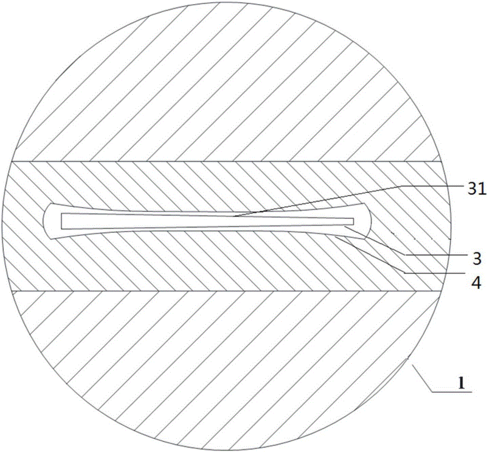
[0051] Wherein, the sizing band 22 of the extrusion die 1 adopted in the step S3 is convex, and the sizing band 22 is located in the axial central area of ​​the die, and is bent radially outward to form an arc-shaped convex portion 31, Such as figure 2 shown.

[0052] In the above-mentioned extrusion die, since the sizing belt 22 is convex, the central area of ​​the pressure is provided with an arc-s...

Embodiment 2

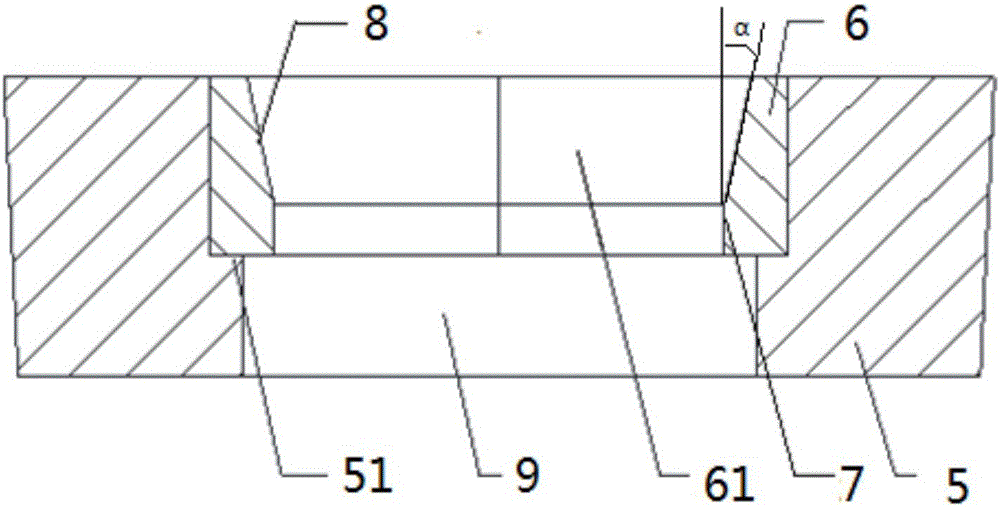
[0067] This embodiment provides a production process for special-shaped silver-copper bars, which is a deformation based on Example 1. In this embodiment, the silver-copper alloy blanks are drawn at least once to obtain special-shaped silver-copper bars. In the step of finished copper bars, the sizing band 7 of the drawing die 6 used is concave, such as image 3 As shown, the part of the sizing belt 7 located in the axial central area of ​​the mold is bent radially inward to form an arc-shaped inner concave part 71, as Figure 4 shown.

[0068] In the drawing die mentioned above, the size of the central part of the cavity formed by the sizing belt 7 is smaller than the size of its two sides. In this way, in the specific drawing operation, although the center of the drawing die is under a large force, the metal filling force is large , but because the size of the cavity in the center is smaller than the size of the cavity on both sides, the filling of the metal in the center i...

Embodiment 3

[0070] This embodiment provides an extrusion die, such as figure 1 As shown, it includes: a mold base 1; a cavity 2, which is arranged on the mold base, and has an inlet 4 and an outlet 3; a sizing belt 22, which is arranged on the mold base 1, and the sizing belt 12 is convex, The portion of the sizing belt 22 located in the pressure center area is bent radially outward to form an arc-shaped convex portion 31, such as figure 2 shown.

[0071] Since the sizing belt 22 is convex, the pressure center area is provided with an arc-shaped convex part 31, so that the inner diameter at this place is originally larger than the inner diameters on both sides. After deformation, all areas at the exit of the sizing belt 33 can reach a straight state , so as to ensure the straight shape of the extruded product from the outlet, and ensure the accuracy of the extruded product and the uniformity of mechanical properties.

[0072] As a preferred embodiment, the mold base 1 is composed of a...


PUM


Abstract

The invention provides a production process for a special-shaped silver-copper busbar and the special-shaped silver-copper busbar. In the step of conducting continuous extrusion on a silver-copper alloy rod so as to manufacture a special-shaped silver-copper alloy busbar blank, a sizing belt 22 of an extrusion die 1 which is adopted is in a protruding shape, and the portion, located on the central area of the die, of the sizing belt 22 is bent outwards in the radial direction to form an arc-shaped outwards-protruding part 31. After a whole base body of the die deforms inwards through high temperature and high pressure, the inward deformation range of the central area is the maximum, and therefore the central area is designed into the arc-shaped protruding part, the size of the central area can be large than that of the two sides, the whole area of an outlet can more tend to the straight state, copper products can evenly flow in the deformation process, straightness of appearance of extruded products coming out of the outlet is ensured, and accuracy of the extruded products and uniformity of the mechanical property are ensured.

Description

technical field [0001] The invention relates to the technical field of metal material processing methods, in particular to a production process of a special-shaped silver-copper bar and the special-shaped silver-copper bar. Background technique [0002] Special-shaped silver-copper bars are more and more widely used in modern industry. The motor commutator in the prior art is generally composed of silver-copper sheets and mica sheets, and the silver-copper sheets are punched and formed by special-shaped silver-copper bars. The copper bar is in the shape of a "knife" or "wedge", that is, one end is large in the thickness direction and the other end is small. It has high requirements on conductivity, hardness and dimensional accuracy, and has a large aspect ratio, with an average aspect ratio of more than 40. , production is more difficult. [0003] At present, the United States and other countries adopt the special-shaped roll rolling method to produce special-shaped silver-...

Claims


Application Information

Patent Timeline
IPC IPC(8): B21C37/00B21C25/02B21C3/02B22D11/14H01B13/00
Inventor 黄四龙李明茂旷军平
Owner JIANGXI GUANGXIN COPPER IND
Learn More