Direct-driven permanent-magnetic wind power generation system active power dynamic control method under voltage drop condition

A wind power generation system and active power technology, applied in wind power generation, control systems, control generators, etc., can solve problems such as increased hardware and software investment of units, high cost of energy storage equipment, and wind abandonment in wind farms.

Active Publication Date: 2015-11-11
HUNAN UNIV
View PDF3 Cites 10 Cited by
  • Summary
  • Abstract
  • Description
  • Claims
  • Application Information

AI Technical Summary

Problems solved by technology

However, such a control strategy has the following disadvantages: 1. When the grid-connected point voltage drops, the active power of the generator-side converter is given according to the maximum power curve, which will cause energy to accumulate on the DC side, causing overvoltage on the DC side ; 2. There is a problem of wind farm abandonment
In view of the above problems, there are currently methods of stabilizing the voltage by installing a bleeder circuit at the DC bus, and methods of stabilizing the voltage by installing an energy storage device at the DC bus, but by installing a bleeder circuit at the DC bus to stabilize the voltage, increasing The hardware and software investment of the unit is increased, and the wind curtailment rate of the wind farm is also indirectly increased; through the method of installing energy storage equipment at the DC bus to stabilize the voltage, although the wind curtailment rate of the wind farm is reduced, the cost of the energy storage equipment high, poor stability
In addition, when the commonly used energy storage devices based on supercapacitors are applied to wind turbines, there are still problems in selection and design.

Method used


Image

  • Direct-driven permanent-magnetic wind power generation system active power dynamic control method under voltage drop condition
  • Direct-driven permanent-magnetic wind power generation system active power dynamic control method under voltage drop condition
  • Direct-driven permanent-magnetic wind power generation system active power dynamic control method under voltage drop condition

Examples


Embodiment Construction

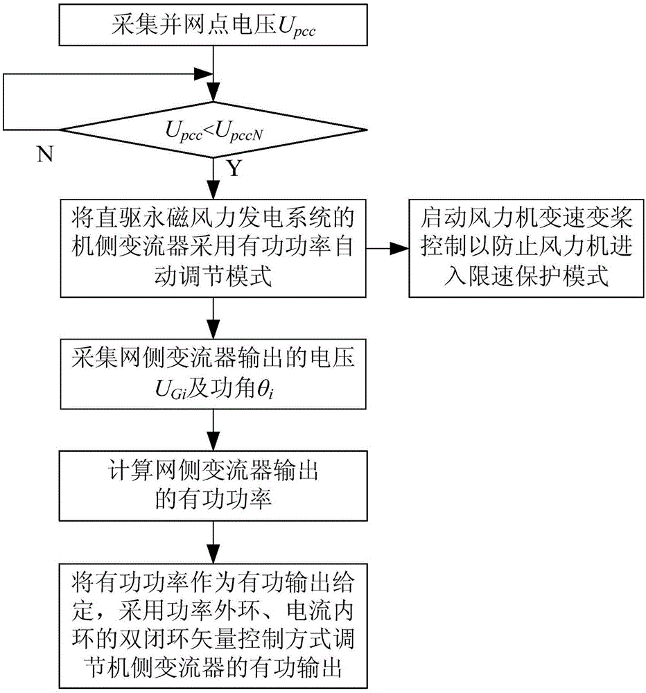
[0050] Such as figure 1 As shown, the steps of the active power dynamic control method of the direct drive permanent magnet wind power generation system when the voltage drops in this embodiment include:

[0051] 1) Collect the grid-connected point voltage U of the direct drive permanent magnet wind power generation system pcc , to determine the grid-connected point voltage U pcc Is it lower than the preset rated value U pccN , if it is lower than the preset rated value, it is determined that a voltage drop occurs and skip to step 2);

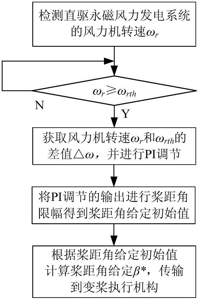
[0052] 2) Enable the active power automatic adjustment mode of the machine-side converter of the direct-drive permanent magnet wind power generation system, and control the variable speed and pitch of the wind turbine to prevent the wind turbine from entering the speed limit protection mode;

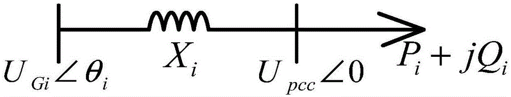
[0053] 3) Collect the output voltage U of the grid-side converter of the direct-drive permanent magnet wind power generation system Gi and power angl...


PUM


Abstract

The invention discloses a direct-driven permanent-magnetic wind power generation system active power dynamic control method under a voltage drop condition. The method includes the following steps that: grid-connection point voltage is acquired, and whether voltage drop occurs is judged; when voltage drop occurs, an active power automatic adjustment mode is enabled for a machine-side converter of a direct-driven permanent-magnetic wind power generation system, and wind turbine variable speed and variable pitch control is enabled so that a wind turbine can be prevented from entering a speed-limiting protection mode; voltage UGi and power angle theta i outputted by a network-side converter of the direct-driven permanent-magnetic wind power generation system are acquired, and active power outputted by the network-side converter is calculated; and the active power is adopted to set the active power output of the machine-side converter, and the active power output of the machine-side converter is adjusted through adopting a double-closed loop vector control mode in which a power outer loop and a current inner loop are adopted. With the method adopted, direct-current side overvoltage caused by energy accumulation at a direct-current side when rid-connection point voltage drops in a wind power plant can be avoided, and wind curtailment of a wind field can be decreased. The method has the advantages of fast response time, low implementation cost as well as being simple and reliable.

Description

technical field [0001] The invention relates to a direct drive permanent magnet wind power generation system, in particular to a dynamic control method for active power of the direct drive permanent magnet wind power generation system when the voltage drops. Background technique [0002] The active power dynamic control system of the machine-side converter of the direct-drive permanent magnet wind power generation system mainly includes the machine-side converter control system and the variable speed and pitch control system. The double-closed-loop vector control method adjusts the active power output of the machine-side converter, and the given active power of the machine-side converter is obtained according to the maximum power curve. However, such a control strategy has the following disadvantages: 1. When the grid-connected point voltage drops, the active power of the generator-side converter is given according to the maximum power curve, which will cause energy to accum...

Claims


Application Information

Patent Timeline
Patent Type & Authority Applications(China)
IPC IPC(8): H02J3/38H02J3/12H02P9/10H02P101/15
CPCY02E10/76
Inventor 黄守道高剑彭婧罗德荣王家堡吕铭晟李慧敏
Owner HUNAN UNIV
Why Eureka
Try Eureka