LDS antenna with silver coatings and manufacturing method of LDS antenna
A silver coating and coating technology, applied in the field of mobile communications, can solve the problems of low production efficiency, high manufacturing cost, complicated production, etc., and achieve the effects of good corrosion resistance, cost reduction, and simple preparation process
- Summary
- Abstract
- Description
- Claims
- Application Information
AI Technical Summary
Problems solved by technology
Method used
Image
Examples
preparation example Construction
[0027] (3) In the preparation method of the silver-plated LDS antenna of the present invention, only two steps are required, the preparation process is simple, and the process of the first electroless plating and the second electroless plating does not need to add cyanide and does not need additional rinsing steps, while the gold coating in the coating structure of copper coating, nickel coating and gold coating in the prior art needs to add cyanide and a rinsing step must be set, which has the advantages of saving raw materials and reducing costs.
[0028] Further, the thickness of the second coating layer is 0.1-1 μm.
[0029] Further, the thickness of the second coating layer is 0.5-1 μm.
[0030] It can be seen from the above description that the thickness of the second silver plating layer can be designed according to actual needs. Preferably, it can be set to 0.1-1 μm, more preferably, it can be set to 0.5-1 μm, which can further ensure good electrical conductivity.
[...
Embodiment 1
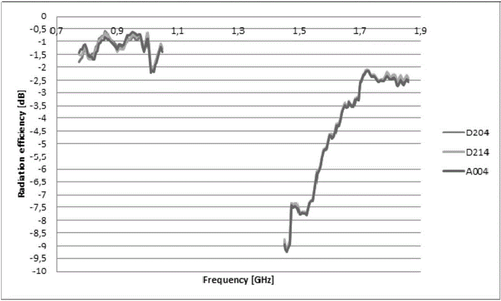
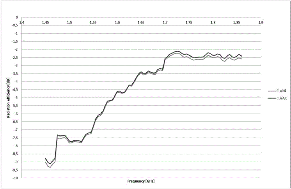
[0039] Please refer to figure 1 and figure 2 , Embodiment 1 of the present invention is:
[0040]A silver-plated LDS antenna in this embodiment includes an antenna element and a coating, the coating is composed of a first coating and a second coating, the first coating is a silver coating or a copper coating, and the second coating is a silver coating , the first coating is disposed on the surface of the antenna element, and the second coating is disposed on the surface of the first coating. The thickness of the second coating layer is 0.1 μm. The thickness of the first coating layer is 5 μm. The antenna element is a MID antenna element. The shapes of the first coating layer and the second silver coating layer are respectively columnar, plate-like, whip-like or parabolic. Silver-plated LDS antennas are communication antennas, broadcast antennas, TV antennas or radar antennas.
[0041] The present invention also provides a method for preparing the above-mentioned silver-...
Embodiment 2
[0043] Only "the thickness of the second coating layer is 1 μm. The thickness of the first coating layer is 15 μm." is different, and the rest of the first embodiment is the same.
PUM
| Property | Measurement | Unit |
|---|---|---|
| Thickness | aaaaa | aaaaa |
| Thickness | aaaaa | aaaaa |
| Thickness | aaaaa | aaaaa |
Abstract
Description
Claims
Application Information
 - R&D
- Intellectual Property
- Life Sciences
- Materials
- Tech Scout
- Unparalleled Data Quality
- Higher Quality Content
- 60% Fewer Hallucinations
Browse by: Latest US Patents, China's latest patents, Technical Efficacy Thesaurus, Application Domain, Technology Topic, Popular Technical Reports.
© 2025 PatSnap. All rights reserved.Legal|Privacy policy|Modern Slavery Act Transparency Statement|Sitemap|About US| Contact US: help@patsnap.com


