

Perovskite solar cell based on doped NiO hole transport layer and preparation method thereof
A solar cell and perovskite technology, applied in circuits, photovoltaic power generation, electrical components, etc., can solve the problems of attenuation, material and interface degradation, battery performance, etc., and achieve high efficiency, stable properties, and improved transmittance.
- Summary
- Abstract
- Description
- Claims
- Application Information
AI Technical Summary
Problems solved by technology
Method used
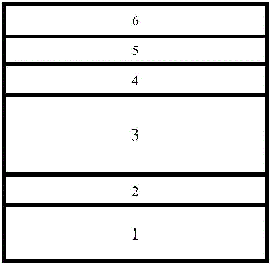
Image

Examples
Embodiment 1
[0039] Step (1) Select FTO glass with a square resistance of 5-25Ω and a transmittance of 70-90% as the substrate, and then clean it with detergent, distilled water, ethanol and acetone.
[0040] Step (2) Preparation of Li or Mg or Li-Mg co-doped NiO dense layer
[0041] Nickel acetylacetonate, lithium acetate or magnesium acetate is used as a source, and according to the stoichiometric ratio Ni:Li:Mg=80:5:15, it is dissolved in an acetonitrile solution with a Ni molar concentration of 0.01-0.04mol / L as a precursor solution. The conductive surface of the FTO glass is placed on a heating platform at 450-600°C, and the precursor solution is sprayed on the heated FTO substrate by atomization spraying method. Continue annealing at this temperature for 10-120 minutes after spraying. Finally, a dense layer of Li or Mg or Li-Mg co-doped NiO is deposited with a thickness of 5-50 nm. Let cool and set aside.
[0042] Step (3) perovskite film (APbX 3 , A=CH 3 NH 3 + or CH(NH 2 ) ...
Embodiment 2
[0051] Except for step two, all steps and methods are exactly the same as in the foregoing embodiment one.
[0052] Step (2) Preparation of non-doped NiO dense layer
[0053] Dissolving nickel acetylacetonate powder without Li and Mg doping raw materials in acetonitrile to obtain a precursor solution with a Ni molar concentration of 0.01-0.04mol / L. The conductive surface of the FTO glass is placed on a heating platform at 450-600°C, and the precursor solution is sprayed on the heated FTO substrate by atomization spraying method. Continue annealing at this temperature for 10-120 minutes after spraying. Finally, a non-doped NiO dense layer with a thickness of 5-50nm is deposited. Let cool and set aside.
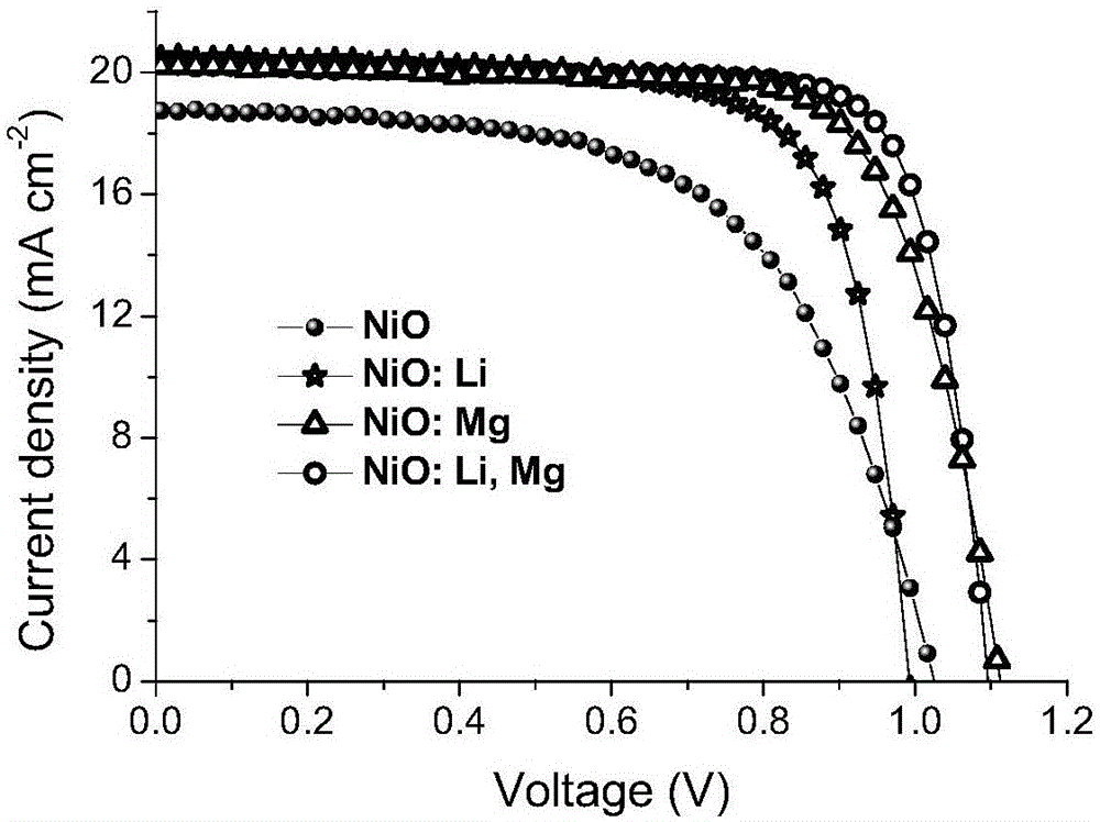
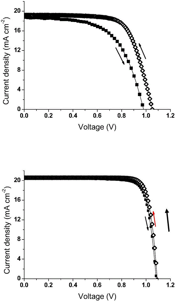
[0054] Implementation effect: Finally, conduct a battery performance test to compare the photoelectric conversion performance of the battery; by changing the voltage scanning method, the voltage scan changes from short circuit to open circuit or from open circuit to short ci...
PUM
| Property | Measurement | Unit |
|---|---|---|
| Thickness | aaaaa | aaaaa |
| Square resistance | aaaaa | aaaaa |
Abstract
Description
Claims
Application Information