Special vertical staggered-tooth adjustable width cutting knife for disk milling slotting of open blisk
A technology of integral blisk and disc milling, applied in milling cutting inserts, milling cutters, manufacturing tools, etc., can solve problems such as low efficiency, and achieve the effects of simple preparation, convenient process, and improved positioning accuracy
- Summary
- Abstract
- Description
- Claims
- Application Information
AI Technical Summary
Problems solved by technology
Method used
Image
Examples
specific Embodiment approach 1
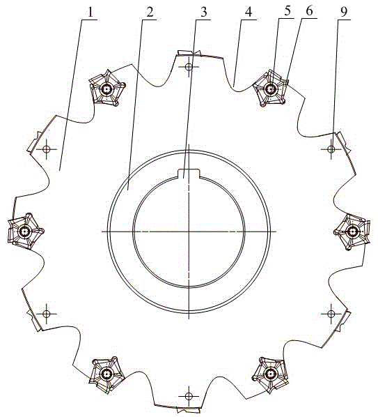
[0021] Specific implementation mode one: combine Figure 1-Figure 4 Note that the vertically-mounted adjustable width cutting tool for milling and slotting of open-type integral blisks in this embodiment adopts a vertically-mounted structure with indexable and staggered teeth to ensure the stability of the tool during processing, which is beneficial to reduce processing time. The vibration of the process mainly includes the cutter body 1 and 12 blades. The material of the cutter body 1 is 42CrMo, which increases the strength of the cutter body. The diameter of the cutter body is 200mm. The center of the cutter body 1 is processed with a central through hole, and the diameter of the central through hole is 50mm. , the center bushing 2 is designed in the center through hole, which is mainly used to connect the milling cutter to the tool holder, and can increase the strength of the tool; the center bushing 2 is designed with an axial keyway 3 for axial positioning, which improves ...
specific Embodiment approach 2
[0023] Specific implementation mode two: combination Figure 1-Figure 4 Note that each flute 4 in this embodiment is composed of two inclined surfaces and an arc surface, the included angle between the inclined surface and the radial direction in the plane of the cutter body is 30°, and the included angle between the two inclined surfaces along the axial direction is 3° °~5°, the inclination direction is the same as the direction of installing the blade, which is easy to curl, break and discharge chips, avoid machining errors caused by poor chip removal during processing, and reduce tool wear;
[0024] A sipe 10 is designed on the top side of the slope of each discharge groove 4, and two positioning grooves 8 are designed in each sipe 10, and two adjacent sipe 4 are designed as a staggered tooth structure.
specific Embodiment approach 3
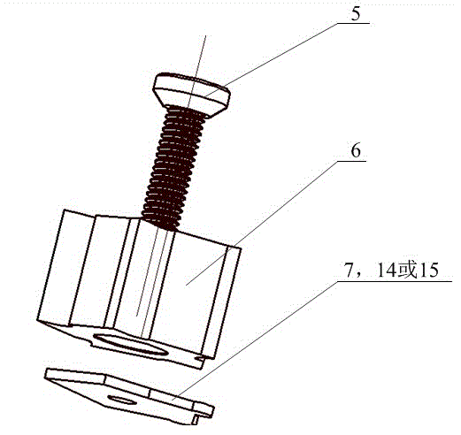
[0025] Specific implementation mode three: combination Figure 1-Figure 4 Explain that each adjusting block 7 of this embodiment is provided with a threaded hole, and the adjusting block 7 is fixed in the knife groove 4 by the fastening screw 5 and the positioning groove 8, and the positioning is simple and accurate;
[0026] When the blade 6 is in the initial position, the blade 6 penetrates the fastening screw 5 and is fixed in the knife groove 4 through the positioning screw hole on the blade and the positioning groove 8 on the cutter body;
[0027] When the blade 6 is shifted by 0.5 mm, an adjustment spacer 7 is designed between the bottom end of the blade 6 and the knife groove 4, and the adjustment spacer 1 7 is fixed in the knife groove 4 by the fastening screw 5 and the positioning groove 8, and the blade 6 And the adjustment block-7 penetrates the fastening screw 5 and is fixed in the knife groove 4 through the positioning groove 8 on the cutter body. When the blade 6...
PUM
 Abstract
Description
Claims
Application Information
 - R&D
- Intellectual Property
- Life Sciences
- Materials
- Tech Scout
- Unparalleled Data Quality
- Higher Quality Content
- 60% Fewer Hallucinations
Browse by: Latest US Patents, China's latest patents, Technical Efficacy Thesaurus, Application Domain, Technology Topic, Popular Technical Reports.
© 2025 PatSnap. All rights reserved.Legal|Privacy policy|Modern Slavery Act Transparency Statement|Sitemap|About US| Contact US: help@patsnap.com


