Laser processing method and device

A laser processing method and laser technology, applied in laser welding equipment, metal processing equipment, manufacturing tools, etc., can solve the problems of increased processing cost, large energy difference between the edge part and the central part, unfavorable laser precision processing, etc., and achieve processing accuracy The effect of high and large aspect ratio

Inactive Publication Date: 2015-11-25
ZHENGZHOU UNIVERSITY OF LIGHT INDUSTRY +1
View PDF3 Cites 39 Cited by
  • Summary
  • Abstract
  • Description
  • Claims
  • Application Information

AI Technical Summary

Problems solved by technology

Therefore, it is necessary to determine the focus position before precision machining. Poor control of the focus position will greatly affect the effect of laser processing. In addition, when processing non-planar materials, it is necessary to control the focus position in real time to ensure that the focus position is always on the surface of the material. surface, which puts forward higher requirements for control technology and increases processing costs
The energy distribution of the processing beam along the diameter direction is Gaussian, that is, the energy in the center of the beam is the highest, and the energy gradually decreases along the radius direction. The energy difference between the edge part and the center part is relatively large, and a certain sharp cone angle will be formed during processing. , which is unfavorable for laser precision machining
In traditional laser processing, the depth-to-diameter ratio (aperture depth / aperture width) has certain limitations. Due to the contradictory relationship between the focal depth of the traditional laser processing lens and the size of the focal spot, it is difficult to improve the resolution and processing depth at the same time.

Method used


Image

  • Laser processing method and device
  • Laser processing method and device
  • Laser processing method and device

Examples


Embodiment 1

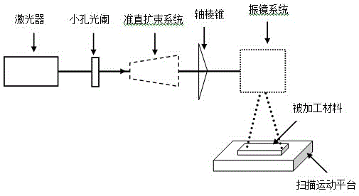
[0028] A laser processing method, the steps are as follows:

[0029] (1) The laser is turned on by the industrial computer control system, so that the laser emits a laser beam.

[0030] The laser should be selected according to the properties of the material to be processed. According to the properties of the material to be processed, the selection of the laser includes the output wavelength, pulse width, etc. The emission wavelength and pulse width are determined according to the properties of the processed material and the processing accuracy requirements. For example, when the material to be processed is an FPCB flexible circuit board, a 355nm ultraviolet laser should be selected. If there is a higher requirement for processing accuracy, ultrashort pulse lasers such as picoseconds or femtoseconds should be selected as the laser light source.

[0031] (2) Let the laser beam pass through the aperture diaphragm to realize the mode selection and radius control of the laser be...

Embodiment 2

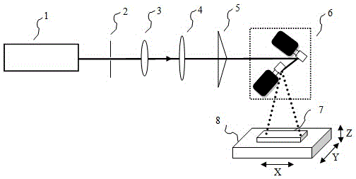
[0040] Such as figure 2 As shown, a laser processing device includes a laser 1 , an aperture stop 2 , a lens I3 , a lens II4 , an axicon optical element 5 , a galvanometer system 6 and a three-dimensional motion platform 8 . The centers of the laser 1 , pinhole diaphragm 2 , lens I3 , lens II4 , axicon optical element 5 and galvanometer system 6 are on a plane, and the three-dimensional motion platform 8 is located below the galvanometer system 6 .

[0041]The aperture diaphragm 2 is an adjustable diaphragm, and its center is the center of the adjustable diaphragm. The beam emitted by the laser 1 passes through the aperture diaphragm 2 and becomes a single-mode laser beam with adjustable beam radius. The processed beam passes through lens I3 and lens II4. The focal lengths of lens I3 and lens II4 are L1 and L2 respectively. When adjusting the optical path, ensure that the beam passes through the center of lens I3 and lens II4, and the distance between lens I3 and lens II4 is...

Embodiment 3

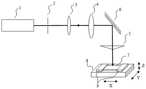
[0045] Such as image 3 As shown, a laser processing device includes a laser 1, a small aperture stop 2, a lens I3, a lens II4, an axicon optical element 5, a mirror 6, and a three-dimensional motion platform 8. The laser 1, the small hole stop 2 The centers of lens I3, lens II4 and mirror 6 are on the horizontal plane, the plane where the centers of axicon optical element 5 and mirror 6 are located is perpendicular to the horizontal plane, and the three-dimensional motion platform 8 is located below the axicon optical element 5.

[0046] The outgoing light beam of the laser 1 passes through the center of the aperture diaphragm 2, the aperture diaphragm 2 is an adjustable aperture, and its center is the center of the adjustable aperture. When the output beam of the laser 1 is multi-mode, adjust the aperture of the aperture stop 2 to block the high-order mode in the outer ring, and only allow the first-order mode to pass through, eliminating the influence of the laser multi-mod...


PUM

PropertyMeasurementUnit
angleaaaaaaaaaa

Abstract

The invention discloses a laser processing method. The method includes the following steps that a laser device is started through a computer control system, so that the laser device emits laser beams; the light beams pass a small-hole diaphragm, so that the functions of mode selection and radius control over the laser beams are achieved; the laser beams passing the small-hole diaphragm are collimated and expanded through a lens set; the collimated and expanded laser beams are converted into Bessel beams through an axicon optical element; and the Bessel beams are emitted to the surface of a processed material through a galvanometer system. The invention further discloses a laser processing device. The position of a focus does not need to be determined during processing, and the laser processing method has the characteristics of being large in depth-diameter ratio, high in precision and the like. The implementation method is simple, an optical path is easy to adjust, and the laser processing method and device have good application prospects in the laser processing field.

Description

technical field [0001] The invention relates to the technical field of laser precision machining, especially the laser cutting, scribing, drilling and other processing fields of glass, solar silicon wafers, LED wafers, PCBs and FPCB boards, and specifically relates to a laser processing method and device. Background technique [0002] Laser precision machining technology has the advantages of non-contact, wide range of processing materials, high precision, high repetition rate, small heat-affected area, and high flexibility in shape and size processing. It is widely used in micro-machines, micro-electronic devices, medical equipment, aviation precision manufacturing, etc. field. The space control and time control of the laser are very good, and the degree of freedom for the material, shape, size and processing environment of the processing object is very large, and it is especially suitable for automatic processing. The combination of laser processing system and computer nu...

Claims


Application Information

Patent Timeline
Patent Type & Authority Applications(China)
IPC IPC(8): B23K26/38B23K26/382B23K26/064
CPCB23K26/0648B23K26/38
Inventor 张培姜利英方洁闫艳霞邓玮崔光照肖小楠周鹏磊
Owner ZHENGZHOU UNIVERSITY OF LIGHT INDUSTRY
Why Eureka
Try Eureka