Spiral-flow type fluidized bed incinerator

An incineration device and fluidized bed technology, applied in the direction of incinerators, combustion methods, combustion types, etc., can solve problems such as waste, insufficient incineration, and uneven particle mixing, so as to reduce the volume of equipment and reduce the carbon content of fly ash The effect of volume and prolonging the residence time

Active Publication Date: 2015-11-25
潍坊联荣环保设备有限公司
View PDF14 Cites 11 Cited by
  • Summary
  • Abstract
  • Description
  • Claims
  • Application Information

AI Technical Summary

Problems solved by technology

[0004] The purpose of the present invention is to provide a swirling fluidized bed incineration device to solve the problem of insufficient incineration caused by uneven particle mixing in the existing fluidized bed combustion process.

Method used


Image

  • Spiral-flow type fluidized bed incinerator
  • Spiral-flow type fluidized bed incinerator
  • Spiral-flow type fluidized bed incinerator

Examples


Embodiment Construction

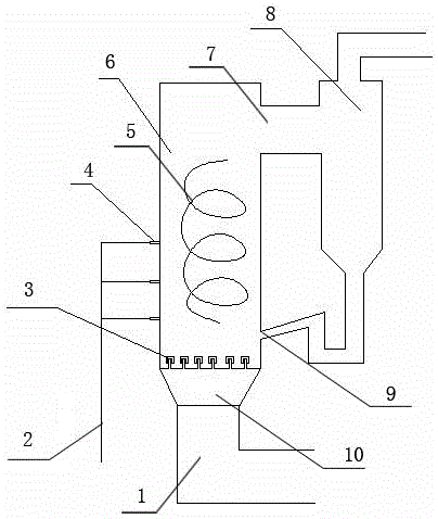
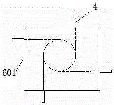
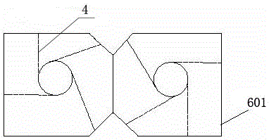
[0024] Figure 1-Figure 9 As shown, the specific implementation is as follows:

[0025] A swirling fluidized bed incineration device, comprising an incinerator 6 providing an incineration space for the fluidized bed, a cyclone separator 8 for recovering insufficiently combusted components for combustion again, and in the inner cavity of the incinerator 6 The lower space forms a dense-phase area, and the upper space forms a dilute-phase area. An air inlet 1 is provided at the bottom of the incinerator 6, and an air distribution plate is arranged between the air inlet 1 and the furnace chamber of the incinerator 6 to distribute air. The plate separates the air inlet 1 from the dense phase area of ​​the incinerator 6 to form an air chamber 10, the gas inlet of the cyclone separator 8 communicates with the gas outlet on the top of the incinerator 6, and the ash outlet of the cyclone separator 8 is connected to the incinerator 6 The feed port at the bottom is connected, and the fu...


PUM


Abstract

The invention discloses a spiral-flow type fluidized bed incinerator which comprises an incinerator body and a cyclone separator. The incinerator body is used for providing combustion space for a fluidized bed, and the cyclone separator is used for recycling insufficiently-combusted ingredients for secondary combustion. At least three layers of secondary air jet orifices are further formed in the walls of the incinerator body and located in a transition zone between a dense-phase zone and a lean-phase zone. The other ends of the secondary air jet orifices are communicated with a secondary air source. The secondary air jet orifices on the same layer are distributed in the walls of the incinerator body. The air flow is spiral so as to enhance transverse mixing of particles and air in the incinerator body and prolong the residence time of the particles in the incinerator body. High-speed secondary air is jetted into the lean-phase zone on the upper portion of an air distribution plate of the circulation fluidized bed incinerator body in a classified manner through wall type tangential firing, so that transverse mixing of particles and air is enhanced, temperature distribution in different areas in the dense-phase zone is more uniform, the combustion efficiency and the desulphurization efficiency are improved, NOx emissions are lowered, the heat transferring is enhanced, and the equipment size is reduced.

Description

technical field [0001] The invention relates to a clean burning device, in particular to a swirling fluidized bed burning device. Background technique [0002] The circulating fluidized bed boiler is a clean combustion equipment. The lower part of the combustion chamber is a dense-phase area, and the upper space is a dilute-phase area. The material density in the furnace is high, and the secondary air penetration is weak. When using anthracite, coal slime, domestic garbage, biomass and other fuels, the gas-solid particles cannot be fully mixed, and the fuel combustion is insufficient. The particles with larger particle sizes can be captured by the cyclone separator and returned to the furnace for re-burning. The fine particles fly out of the furnace and pass through the cyclone separator at one time, and its burnout rate is low, resulting in a high carbon content in the fly ash in the tail flue. If the circulating fluidized bed adopts a special layout method, by changing th...

Claims


Application Information

Patent Timeline
Patent Type & Authority Applications(China)
IPC IPC(8): F23G5/30
Inventor 王学涛段景卫兰维娟刘春梅田中君
Owner 潍坊联荣环保设备有限公司
Why Eureka
Try Eureka