Compressor lubricating oil cooling system and control method thereof

A cooling system and lubricating oil technology, applied in refrigerators, refrigeration components, mechanical equipment, etc., can solve problems such as maintaining stability, reducing compressor sealing, and not easily forming oil films, improving volumetric efficiency, reducing variation, and avoiding The effect of frequent start and stop

Active Publication Date: 2015-12-02
PANASONIC APPLIANCES REFRIGERATION SYST DALIAN CO LTD
View PDF8 Cites 18 Cited by
  • Summary
  • Abstract
  • Description
  • Claims
  • Application Information

AI Technical Summary

Problems solved by technology

When the external environment temperature changes, the oil cooling load changes greatly, and the cooling capacity of the system for lubricating oil also changes greatly, which makes it difficult to keep the lubricating oil return temperature stable within the specified range
[0005] The traditional control method has the following defects when the system is working: due to the influence of the external environment and the operating load of the system, the cooling load of the lubricating oil is constantly changing, and it is difficult to select a throttling device with a suitable specification to stabilize the return temperature of the lubricating oil within the specified range
Excessively high lubricating oil return temperature will reduce its viscosity and reduce the lubricity of the moving parts of the compressor. Excessively high lubricating oil return temperature will also lead to excessively high discharge temperature of the compressor, which may cause the compressor to malfunct

Method used


Image

  • Compressor lubricating oil cooling system and control method thereof
  • Compressor lubricating oil cooling system and control method thereof

Examples


Embodiment Construction

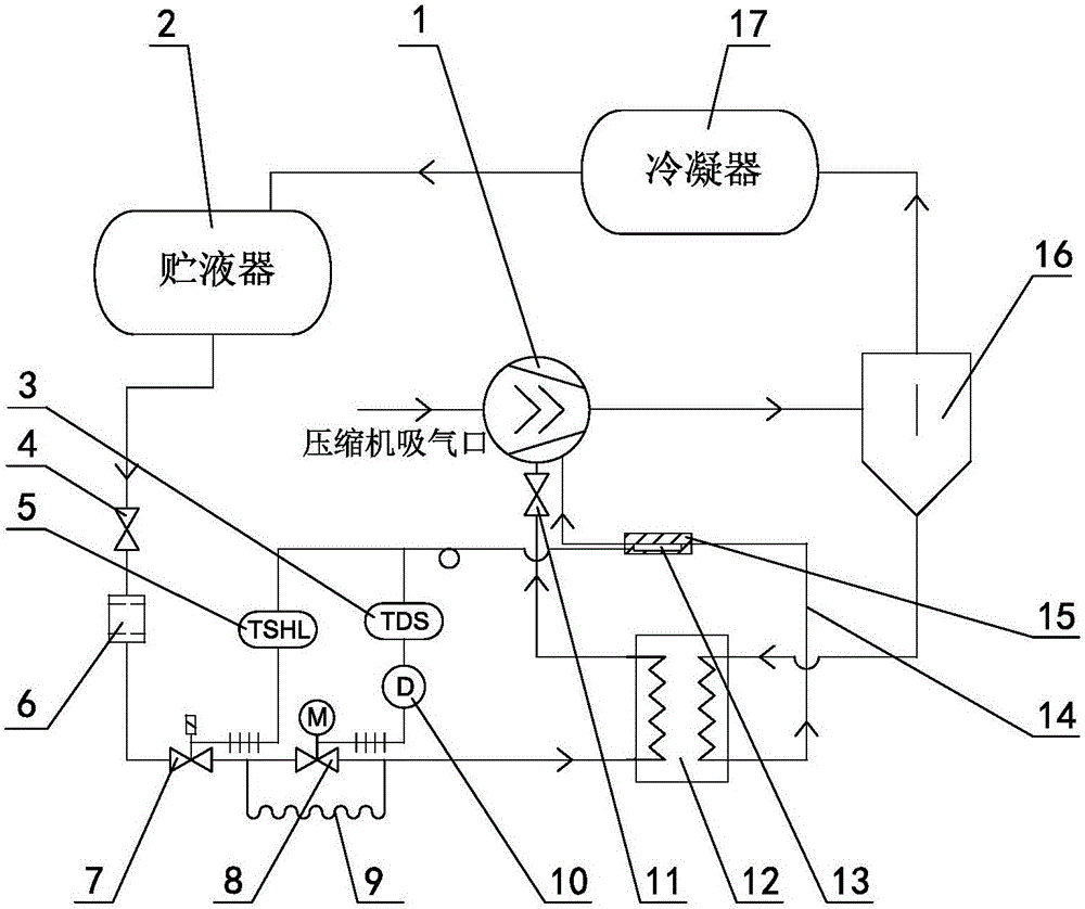
[0020] A compressor lubricating oil cooling system is suitable for refrigerating units in the refrigerating and freezing industry.

[0021] In order to make the purpose, technical solutions and advantages of the embodiments of the present invention clearer, the technical solutions in the embodiments of the present invention will be clearly and completely described below in conjunction with the drawings in the embodiments of the present invention. Obviously, the described embodiments It is a part of embodiments of the present invention, but not all embodiments. Based on the embodiments of the present invention, all other embodiments obtained by persons of ordinary skill in the art without making creative efforts belong to the protection scope of the present invention.

[0022] Such as figure 1 A compressor lubricating oil cooling system shown is characterized in that it includes a compressor 1, an oil separator 16, a condenser 17, a liquid reservoir 2, a liquid reservoir outle...


PUM


Abstract

The invention discloses a compressor lubricating oil cooling system. The compressor lubricating oil cooling system is characterized by comprising a compressor, an oil separator, a condenser, a liquid reservoir, a liquid reservoir outlet stop valve, a drying filter, a solenoid valve, an electronic expansion valve and a plate type heat exchanger which are sequentially communicated through a pipeline, wherein a lubricating oil outlet of the plate type heat exchanger is communicated with the compressor through an oil supply tube; a temperature sensor for measuring a lubricating oil reflux temperature is arranged on the oil supply tube; the temperature sensor is electrically connected with the electronic expansion valve through a series controller and an electronic expansion valve driver; and the temperature sensor is electrically connected with the solenoid valve through a series temperature switch. The invention further discloses a control method for the compressor lubricating oil cooling system. According to the compressor lubricating oil cooling system and the control method thereof, the oil return temperature of the lubricating oil can be kept stable; the fault rate of the compressor is reduced; and the service life of the plate type heat exchanger is prolonged.

Description

technical field [0001] The invention relates to the refrigeration field, in particular to a compressor lubricating oil cooling system and a control method thereof. Background technique [0002] At present, in refrigeration units used in the refrigeration industry, the high-temperature lubricating oil separated by the oil separator after the compressor is exhausted is mostly used to throttle the condensed liquid refrigerant and directly evaporate and exchange heat in the plate heat exchanger. cooling method. The cooled lubricating oil flows back into the compressor to lubricate and cool moving parts such as bearings. The traditional lubricating oil cooling system mostly uses devices such as thermal expansion valves or orifice plates to throttle the liquid refrigerant, and the thermostat controls the start and stop of the liquid supply solenoid valve according to the temperature of the lubricating oil after cooling. [0003] The Chinese patent application number 201110276326...

Claims


Application Information

Patent Timeline
IPC IPC(8): F25B41/04F25B41/06F25B49/02F04C29/04F25B41/20F25B41/31F25B41/37
CPCY02B30/70
Inventor 吴剑光单永明王有佐高鹏杨勃朱卫英苏梅
Owner PANASONIC APPLIANCES REFRIGERATION SYST DALIAN CO LTD
Why Eureka
Try Eureka