A waste flue gas heat recovery system and its application method

A waste heat recovery system and heat recovery technology, applied in the field of heat recovery systems, can solve the problems of low heat exchange efficiency, increased cost, poor equipment applicability, etc., and achieve the effect of good thermal vibration resistance and shortened service life.

Active Publication Date: 2017-08-29
YIXING HAINA ENVIRONMENTAL ENG
View PDF6 Cites 0 Cited by
  • Summary
  • Abstract
  • Description
  • Claims
  • Application Information

AI Technical Summary

Problems solved by technology

[0003] With social progress and environmental protection requirements, flue gas waste heat recovery technology has gradually matured and has begun to be applied to actual production. In general industrial production processes, the flue gas after combustion and heating is only recovered part of the apparent gas through heat storage bricks. , and then directly discharged into the atmosphere through the main chimney. In fact, the waste heat of the flue gas entering the chimney through the main flue still has a large recycling value. The low resource utilization rate not only increases the production cost, but also affects the quality of the atmosphere. , the current flue gas waste heat recovery technology has the defects of low heat exchange efficiency and poor applicability of equipment

Method used


Image

  • A waste flue gas heat recovery system and its application method

Examples


Embodiment 1

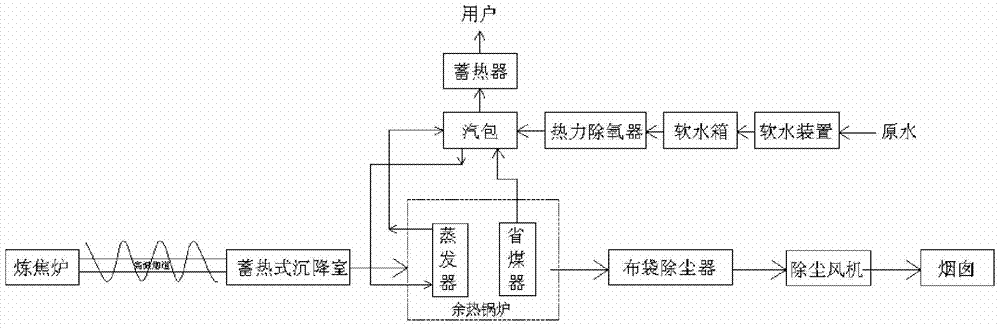
[0032] A waste flue gas heat recovery system provided in this embodiment has a structure such as figure 1 As shown, it includes the coke oven, waste heat recovery system and chimney, the inlet end of the waste heat recovery system is connected to the coke oven, and the outlet end of the waste heat recovery system is connected to the chimney, where:

[0033] The waste heat recovery system includes a steam drum, a waste heat boiler and a heat accumulator. The waste heat boiler is equipped with an evaporator and an economizer along the direction of flue gas circulation. The top of the waste heat boiler is provided with a steam drum that provides steam to users. The outlet of the steam drum The end is connected to the heat accumulator, the outlet of the economizer is connected to the steam drum, the downcomer of the steam drum is connected to the inlet of the evaporator, and the outlet of the steam-water mixture of the evaporator is connected to the steam drum;

[0034] The waste ...

Embodiment 2

[0045] A waste flue gas heat recovery system provided in this embodiment has a structure such as figure 1As shown, it includes the coke oven, waste heat recovery system and chimney, the inlet end of the waste heat recovery system is connected to the coke oven, and the outlet end of the waste heat recovery system is connected to the chimney, where:

[0046] The waste heat recovery system includes a steam drum, a waste heat boiler and a heat accumulator. The waste heat boiler is equipped with an evaporator and an economizer along the direction of flue gas circulation. The top of the waste heat boiler is provided with a steam drum that provides steam to users. The outlet of the steam drum The end is connected to the heat accumulator, the outlet of the economizer is connected to the steam drum, the downcomer of the steam drum is connected to the inlet of the evaporator, and the outlet of the steam-water mixture of the evaporator is connected to the steam drum;

[0047] The waste h...

Embodiment 3

[0058] A waste flue gas heat recovery system provided in this embodiment has a structure such as figure 1 As shown, it includes the coke oven, waste heat recovery system and chimney, the inlet end of the waste heat recovery system is connected to the coke oven, and the outlet end of the waste heat recovery system is connected to the chimney, where:

[0059] The waste heat recovery system includes a steam drum, a waste heat boiler and a heat accumulator. The waste heat boiler is equipped with an evaporator and an economizer along the direction of flue gas circulation. The top of the waste heat boiler is provided with a steam drum that provides steam to users. The outlet of the steam drum The end is connected to the heat accumulator, the outlet of the economizer is connected to the steam drum, the downcomer of the steam drum is connected to the inlet of the evaporator, and the outlet of the steam-water mixture of the evaporator is connected to the steam drum;

[0060] The waste ...


PUM


Abstract

The invention discloses a waste smoke heat recovery system. The waste smoke heat recovery system comprises a coke oven, an afterheat recovery system and a chimney, wherein the afterheat recovery system comprises a steam pocket, an afterheat boiler and a heat accumulator; the afterheat boiler is provided with an evaporator and a coal economizer in a smoke circulation direction, and is connected with a thermal deaerator through the steam pocket; an inlet end of the thermal deaerator is connected with a soft water tank; a soft water device is arranged at an inlet end of the soft water tank; a heat accumulation type settling chamber is arranged between the afterheat recovery system and the coke oven, and is connected with the coke oven through a high-temperature flue; the high-temperature flue is wound with a water pipe; water circularly flows in the water pipe; and a cloth bag dust collector and a dust removing fan are arranged between the afterheat recovery system and the chimney in sequence. The invention further designs an application method of the waste smoke heat recovery system; the waste smoke heat recovery system is simple in structure and feasible, can preferably recover afterheat in waste smoke of the coke oven, and effectively uses resources to prevent the resource waste; and the application method is simple and feasible.

Description

technical field [0001] The invention relates to a heat recovery system and its application method, in particular to a waste flue gas heat recovery system and its application method. Background technique [0002] Heat energy is widely used, it can be directly applied in life and production, such as air conditioning, metallurgy, textile, chemical industry, papermaking and other fields, and can also be converted into other forms of energy, such as electrical energy, mechanical energy, etc. It is formed by converting chemical energy into water vapor or flue gas. The fuel is burned to convert the chemical energy in it into heat energy carried by the combustion products. The carrier is flue gas. [0003] With social progress and environmental protection requirements, flue gas waste heat recovery technology has gradually matured and begun to be applied to actual production. In the general industrial production process, the flue gas after combustion and heating is only recovered par...

Claims


Application Information

Patent Timeline
Patent Type & Authority Patents(China)
IPC IPC(8): F22B1/18F22D1/50F27D17/00F23J13/02
CPCY02P10/25
Inventor 张忠其张栩婕
Owner YIXING HAINA ENVIRONMENTAL ENG
Why Eureka
Try Eureka