Sub-millimeter spatial resolution distributed optical fiber sensing device and method

A technology of spatial resolution and distributed optical fiber, applied in the direction of using optical devices, using optical devices to transmit sensing components, measuring devices, etc., can solve the problem of low spatial resolution and the inability of distributed optical fiber sensing systems to balance spatial resolution and Sensing distance, limited sensing distance and other issues, to achieve the effect of extending the sensing distance and overcoming the spatial resolution and sensing distance

Active Publication Date: 2015-12-09
TAIYUAN UNIV OF TECH
View PDF9 Cites 31 Cited by
  • Summary
  • Abstract
  • Description
  • Claims
  • Application Information

AI Technical Summary

Problems solved by technology

[0006] In order to solve the problems that the existing distributed optical fiber sensing system cannot balance the spatial resolution and sensing distance, the sensing distance is severely limited, and the spatial resolution is low, the present invention provides a distributed optical fiber sensing system with submillimeter spatial resolution. Sensing device and method

Method used


Image

  • Sub-millimeter spatial resolution distributed optical fiber sensing device and method

Examples


Embodiment Construction

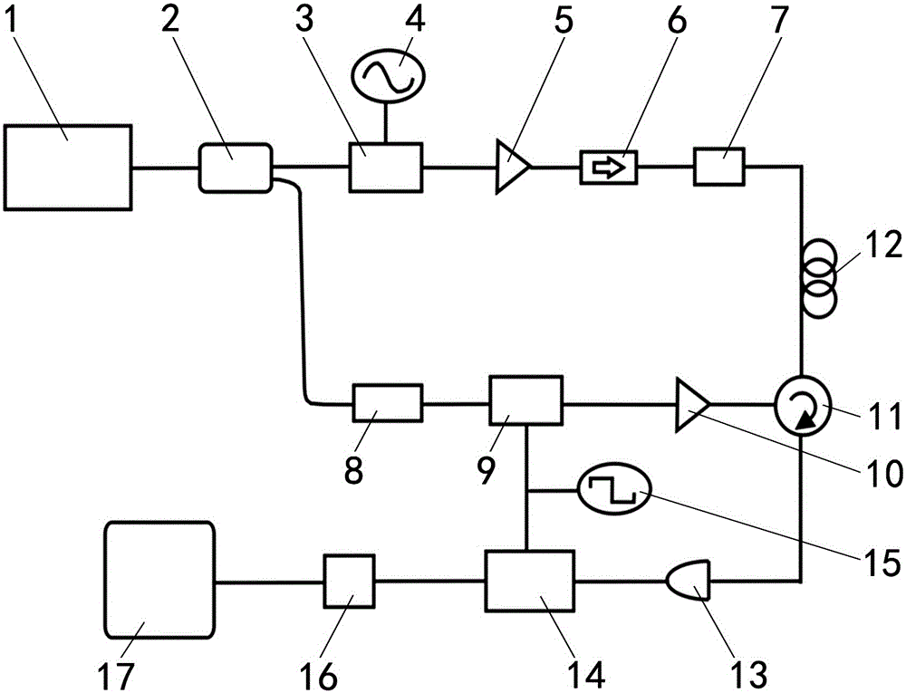
[0019] A distributed optical fiber sensing device with submillimeter spatial resolution, comprising a chaotic laser 1, a 1×2 fiber coupler 2, a high-speed electro-optic modulator 3, a microwave signal source 4, a first optical amplifier 5, an optical isolator 6, Optical scrambler 7, variable optical delay line 8, low-speed electro-optic modulator 9, second optical amplifier 10, optical circulator 11, sensing fiber 12, photodetector 13, lock-in amplifier 14, signal generator 15, Data acquisition card 16, computer 17;

[0020] Wherein, the output end of the chaotic laser 1 is connected with the input end of the 1×2 fiber coupler 2;

[0021]The first output end of the 1×2 fiber optic coupler 2 is connected to the input end of the high-speed electro-optic modulator 3 through a single-mode fiber jumper; the output end of the high-speed electro-optic modulator 3 is connected to the first optical amplifier 5 through a single-mode fiber jumper The incident end of the microwave signal...


PUM

PropertyMeasurementUnit
wavelengthaaaaaaaaaa
lengthaaaaaaaaaa

Abstract

The invention relates to a distributed optical fiber sensing system, and specifically relates to a sub-millimeter spatial resolution distributed optical fiber sensing device and method. According to the invention, the problems of unavailable spatial resolution and sensing distance combination, seriously limited sensing distance and low spatial resolution of the existing distributed optical fiber sensing system are solved. The sub-millimeter spatial resolution distributed optical fiber sensing device comprises a chaos laser, a 1*2 optical fiber coupler, a high-speed electro-optic modulator, a microwave signal source, a first optical amplifier, an optical isolator, an optical scrambler, an variable optical delay line, a low-speed electro-optic modulator, a second optical amplifier, an optical circulator, a sensing optical fiber, a photodetector, a phase-lock amplifier, a signal generator, a data acquisition card and a computer. The device and the method, which are provided by the invention, are applicable to the field of distributed optical fiber sensing.

Description

technical field [0001] The invention relates to a distributed optical fiber sensing system, in particular to a distributed optical fiber sensing device and method with submillimeter spatial resolution. Background technique [0002] Distributed optical fiber sensing system has been widely used in aerospace, petrochemical, electric power industry, nuclear industry, civil engineering due to its advantages of distributed measurement, long monitoring distance, high spatial resolution, fast response time, anti-electromagnetic interference and military fields. At present, distributed optical fiber sensing systems can be divided into the following three types according to the scattering mechanism in optical fibers: distributed optical fiber sensing systems based on Rayleigh scattering, distributed optical fiber sensing systems based on Raman scattering, and distributed optical fiber sensing systems based on Brillouin scattering. distributed optical fiber sensing system. Among them...

Claims


Application Information

Patent Timeline
Patent Type & Authority Applications(China)
IPC IPC(8): G01D5/353G01K11/32G01B11/16G01K11/322
Inventor 张建忠张明江刘毅王云才张明涛冯昌坤
Owner TAIYUAN UNIV OF TECH
Why Eureka
Try Eureka