Polarized RFID system without chips

A chipless, horizontally polarized technology, applied to collaborative devices, instruments, computing, etc., can solve the problems of increased difficulty in circuits and signal processing circuits, high price of SAW tags, and large size of tag antennas to improve anti-interference capability, production cost reduction, and system cost reduction effect

Active Publication Date: 2015-12-09
NANJING UNIV OF SCI & TECH
View PDF4 Cites 24 Cited by
  • Summary
  • Abstract
  • Description
  • Claims
  • Application Information

AI Technical Summary

Problems solved by technology

[0003] More and more engineers are turning to the design of chipless RFID tags. The chipless RFID technologies involved in the public literature are mainly divided into three categories: 1. Chipless tags based on time domain reflectometer (TDR), such as based on acoustic Surface wave (SAW) passive tags, but SAW tags are more expensive and difficult to bend
2. Chipless tags based on spectral characteristics, such as passive tags based on multi-resonators, generally consist of a receiving antenna, a resonant circuit and a transmitting antenna, which need to transmit signals with a wide spectrum, limited coding capacity, and relatively large size
Md.AminulIslam et al. combined method 2 and method 3 in "CompactPrintableChiplessRFIDTagsUsingPolarizationDiversity" using polarization characteristics to design a square chipless RFID tag antenna with horizontal and vertical slits, and simultaneously transmit horizontal and vertical polarizations with a wide spectrum The electromagnetic wave signal is encoded b

Method used


Image

  • Polarized RFID system without chips
  • Polarized RFID system without chips
  • Polarized RFID system without chips

Examples


Embodiment 1

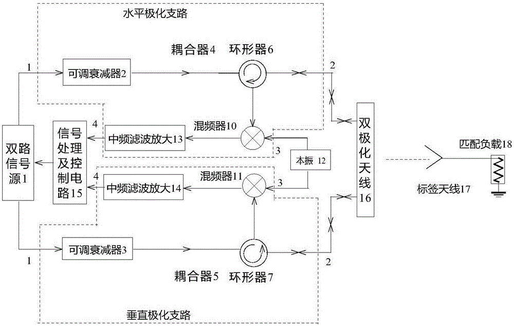
[0024]A chipless RFID system with variable polarization, including a dual signal source 1, a horizontal polarization branch, a vertical polarization branch, a signal processing and control circuit 15, a local oscillator 12, a dual-polarization antenna 16, and a tag antenna 17 , matching load 18. The horizontal polarization branch includes a first adjustable attenuator 2 , a first circulator 6 , a first mixer 10 , and a first intermediate frequency filter amplifier 13 . The vertical polarization branch includes a first adjustable attenuator 3 , a first circulator 7 , a first mixer 11 , and a first intermediate frequency filter amplifier 14 . The two output terminals of the dual signal source 1 are respectively connected to the input terminals of the first adjustable attenuator 2 and the second adjustable attenuator 3 . The output end of the second adjustable attenuator 2 is connected with the first port of the first circulator 6, and the second port of the first circulator 6 i...

Embodiment 2

[0028] A chipless RFID system with variable polarization, including a dual signal source 1, a horizontal polarization branch, a vertical polarization branch, a signal processing and control circuit 15, a local oscillator 12, a dual-polarization antenna 16, and a tag antenna 17 , matching load 18. The horizontal polarization branch includes a first adjustable attenuator 2 , a first circulator 6 , a first mixer 10 , and a first intermediate frequency filter amplifier 13 . The vertical polarization branch includes a first adjustable attenuator 3 , a first circulator 7 , a first mixer 11 , and a first intermediate frequency filter amplifier 14 . The two output terminals of the dual signal source are respectively connected to the first port of the horizontal polarization branch and the first port of the vertical polarization branch, and the second terminal of the horizontal polarization branch and the second terminal of the vertical polarization branch are respectively Connected t...

Embodiment 3

[0034] A chipless RFID system with variable polarization, including a dual signal source 1, a horizontal polarization branch, a vertical polarization branch, a signal processing and control circuit 15, a local oscillator 12, a dual-polarization antenna 16, and a tag antenna 17 , matching load 18. The horizontal polarization branch includes a first adjustable attenuator 2 , a first circulator 6 , a first mixer 10 , and a first intermediate frequency filter amplifier 13 . The vertical polarization branch includes a first adjustable attenuator 3 , a first circulator 7 , a first mixer 11 , and a first intermediate frequency filter amplifier 14 . The two output terminals of the dual signal source 1 are respectively connected to the input terminals of the first adjustable attenuator 2 and the second adjustable attenuator 3 . The output end of the second adjustable attenuator 2 is connected with the first port of the first circulator 6, and the second port of the first circulator 6 ...


PUM


Abstract

The invention provides a polarized RFID (radio frequency identification) system without chips. The polarized RFID system without chips comprises a double channel signal source, a horizontal polarization branch circuit, a vertical polarization branch circuit, a dual polarization antenna, and a signal processing and control circuit, wherein the double channel signal source can generate two channels of radiofrequency signals with the same frequency and controllable phase at will; the horizontal polarization branch circuit adjusts the amplitude of the first channel of radiofrequency signal during the signal emission process, and performs frequency mixing for a reflected signal and a local oscillator signal during the process of receiving the reflected signal, and performs filtering and amplification when the frequency conversion is taken down; the vertical polarization branch circuit adjusts the amplitude of the second channel of radiofrequency signal during the signal emission process, and performs frequency mixing for a reflected signal and a local oscillator signal during the process of receiving the reflected signal, and performs filtering and amplification when the frequency conversion is taken down; the dual polarization antenna emits two channels of radiofrequency signals with adjustable amplitude and phase, and can stimulate a pair of linear polarization electromagnetic waves which are vertical in the polarized direction; the two channels of linear polarization electromagnetic waves can be overlaid with any polarized electromagnetic waves, and can receive the reflected signal; and the signal processing and control circuit is used for adjusting the phase difference between two channels of radiofrequency signals, and is used for coding the reflected signal.

Description

technical field [0001] The invention relates to radio frequency communication and short-range detection technology, in particular to a chipless RFID system based on a scheme of variable polarization. Background technique [0002] Radio Frequency Identification (RFID) is a non-contact automatic identification technology implemented by radio frequency communication. It automatically identifies target objects and obtains relevant data information through radio frequency signals. The process requires no human intervention. RFID technology is widely used in various industries such as logistics, aviation, animal husbandry, mobile commerce, ticket management, production line automation, etc., and is considered to be one of the ten most promising technologies in the 21st century. With the widespread application, RFID technology is becoming more and more powerful. When the production quantity increases sharply, the demand for reducing the cost of RFID becomes more and more intense. ...

Claims


Application Information

Patent Timeline
IPC IPC(8): G06K17/00
Inventor 余云忠陈春红吴文方超廖明张新鹏
Owner NANJING UNIV OF SCI & TECH
Why Eureka
Try Eureka