
Friction-stir welding device and method for motor rotor

A motor rotor and friction stir technology, which is applied in welding equipment, non-electric welding equipment, metal processing equipment, etc., can solve the problems of high cost of automation special equipment, overcome the bottleneck of surface treatment, improve electrical conductivity and quality, and reduce defects Effect

Inactive Publication Date: 2015-12-23
SHANGHAI JIAO TONG UNIV +1
View PDF11 Cites 6 Cited by
  • Summary
  • Abstract
  • Description
  • Claims
  • Application Information

AI Technical Summary

Problems solved by technology

Although foreign countries with advanced equipment have realized the automation of induction brazing and can obtain smooth and firm welded joints, due to the high cost of automation special equipment, they cannot be accepted by domestic enterprises, as described in the invention patent with the authorized announcement number CN100469502C

Method used


Image

  • Friction-stir welding device and method for motor rotor
  • Friction-stir welding device and method for motor rotor

Examples


Embodiment 1

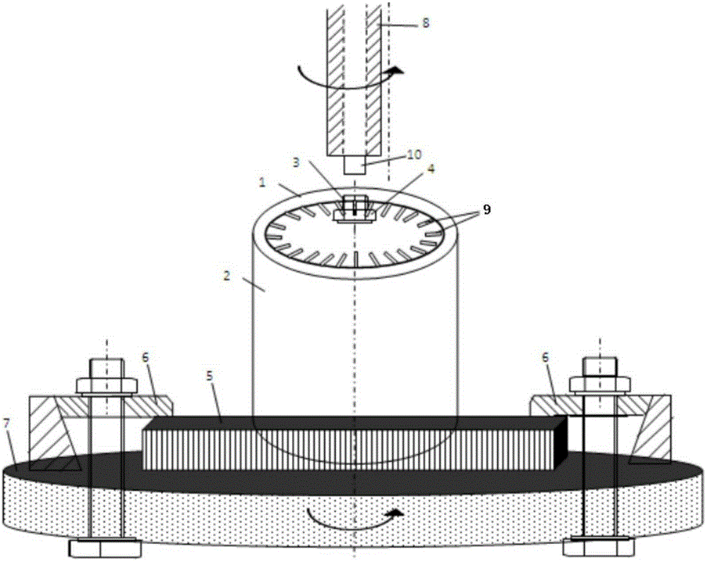
[0031] Refer to attached figure 1 , the present embodiment provides a friction stir welding device for a motor rotor, which includes 1. an end face of the motor rotor to be welded, 2. a sleeve, 3. a screw, 4. a nut, 5. a fixing plate, 6. a pressing plate, 7. .Turntable, 8. Stirring head, 9. Guide bar, 10. Stirring needle.

[0032] Specifically include the following steps:

[0033] 1. Tooling preparation and clamping: The outer diameter of one end face 1 of the motor rotor to be welded is Φ99.913mm, the height is 150.00mm, the inner diameter of the sleeve 2 is Φ100.052mm, and the height is 150.50mm. First, the sleeve 2 and the motor rotor to be welded are installed on the fixed plate 5 through the screw rod 3 and the nuts 4 at both ends thereof, and the fixed plate 5 can be fixed on a horizontally rotatable turntable 7 by a pressing plate 6 . The center of circle of the motor rotor to be welded coincides with the center of circle of the turntable 7 .

[0034] 2. Welding: fir...

Embodiment 2

[0042] With reference to Example 1, wherein the rotational speed of the stirring head is 1500rpm, the speed at which the stirring needle is inserted into the end face of the motor rotor to be welded is 50mm / min, the depression of the shoulder is 0.1mm, and the residence time is 10s. The rotational speed of the turntable is 200° / min, the retraction process is completed in a 50° journey. All the other are identical with embodiment 1.

Embodiment 3

[0044] With reference to Example 1, wherein the rotational speed of the stirring head is 500rpm, the speed at which the stirring needle is inserted into the end face of the motor rotor to be welded is 15mm / min, the depression of the shoulder is 0.3mm, the residence time is 30s, and the rotational speed of the turntable is 100° / min, the retraction process is completed in a 80° journey. All the other are identical with embodiment 1.


PUM

PropertyMeasurementUnit
heightaaaaaaaaaa
heightaaaaaaaaaa

Abstract

The invention relates to a friction-stir welding device and method for a motor rotor. The friction-stir welding device comprises a sleeve, a fixed plate and a rotary table. The friction-stir welding method comprises the steps that firstly, the motor rotor to be welded and the welding device are fixed to the rotary table; secondly, a stirring head is inserted in one end face of the rotor to be welded, and welding is started while the rotary table rotates; thirdly, after the rotary table rotates by a circle, a stirring needle starts to be drawn back till the stirring needle completely retracts to the surface of the end face of the rotor to be welded; and finally, the rotor to be welded is taken out and turned, and welding of the other end face of the rotor to be welded is completed in the same way. According to the friction-stir welding device and method for the motor rotor, simple tools and a friction-stir welding technique high in operability are adopted. Due to the fact that friction-stir welding is solid connection, deformation of the rotor is small; meanwhile, oxide layers of end rings and oxide layers of guide strips are broken through friction stir, the welding strength and welding quality of an interface are obviously improved, and the unsurmountable defect of manual welding and induction soldering that surface treatment needs to be conducted is overcome; by the adoption of the method, energy consumption for welding is low, noise is low, and the influence on the environment is small.

Description

technical field [0001] The invention belongs to the field of welding, and in particular relates to a friction stir welding device and method for a motor rotor. Background technique [0002] Squirrel-cage three-phase asynchronous motors have been widely used in various fields such as daily life, factory equipment, ports, oilfields and coal mines due to their simple structure, low maintenance cost, and long service life. At present, the structure of the rotor part is basically formed by punching and laminating multiple silicon steel sheets with a thickness of 0.5mm. The ends are connected with a shorting ring. The connection method of the conductor and the short-circuit ring is generally welded or directly cast into one body. Casting is not as widely used as welding due to low yield and poor quality. And the welding process adopts induction heating brazing or gas flame brazing (as described in the invention patents of CN102922074B, CN103028857B, and CN100469502C). Due to t...

Claims


Application Information

Patent Timeline
Patent Type & Authority Applications(China)
IPC IPC(8): B23K20/12B23K20/26
CPCB23K20/129B23K20/26
Inventor 郑飞燕陈娟叶兵朱永奎彭立明
Owner SHANGHAI JIAO TONG UNIV
Features
  • Generate Ideas
  • Intellectual Property
  • Life Sciences
  • Materials
  • Tech Scout
  • Unparalleled Data Quality
  • Higher Quality Content
  • 60% Fewer Hallucinations
Learn More