
Centrifugal shot blasting electroforming manufacturing method and device

A technology for manufacturing devices and manufacturing methods, which is applied in the field of centrifugal shot peening electroforming manufacturing methods and devices, which can solve the problems of uneven materials, even delamination, and mechanical performance degradation of parts on the upper and lower layers of the deposition layer, so as to improve the deposition speed of electroforming , Inhibition of build-up and pits, and improvement of fatigue strength

Active Publication Date: 2015-12-23
JIANGSU UNIV
View PDF6 Cites 5 Cited by
  • Summary
  • Abstract
  • Description
  • Claims
  • Application Information

AI Technical Summary

Problems solved by technology

However, due to the effect of gravity, the electroformed layer of the mandrel buried in the bottom layer receives a large extrusion friction force, and the electroformed layer of the mandrel buried in the surface layer receives a small extrusion friction force, which will still cause uneven materials on the upper and lower sides of the deposition layer.
[0004] There are other methods to improve the quality of electrodeposition manufacturing, such as interrupting the deposition process, removing surface tumors and burrs through mechanical processing, and then performing secondary deposition; or using additives to improve the electrodeposition liquid formula, increasing the electrodeposition liquid temperature, changing Stirring speed and method, etc., but the processing effect is not ideal, and the obtained deposit layer often has defects such as cracks and even delamination, which reduces the mechanical properties of the parts

Method used


Image

  • Centrifugal shot blasting electroforming manufacturing method and device
  • Centrifugal shot blasting electroforming manufacturing method and device

Examples


Embodiment Construction

[0027] The present invention will be further described below in conjunction with the accompanying drawings and specific embodiments, but the protection scope of the present invention is not limited thereto.

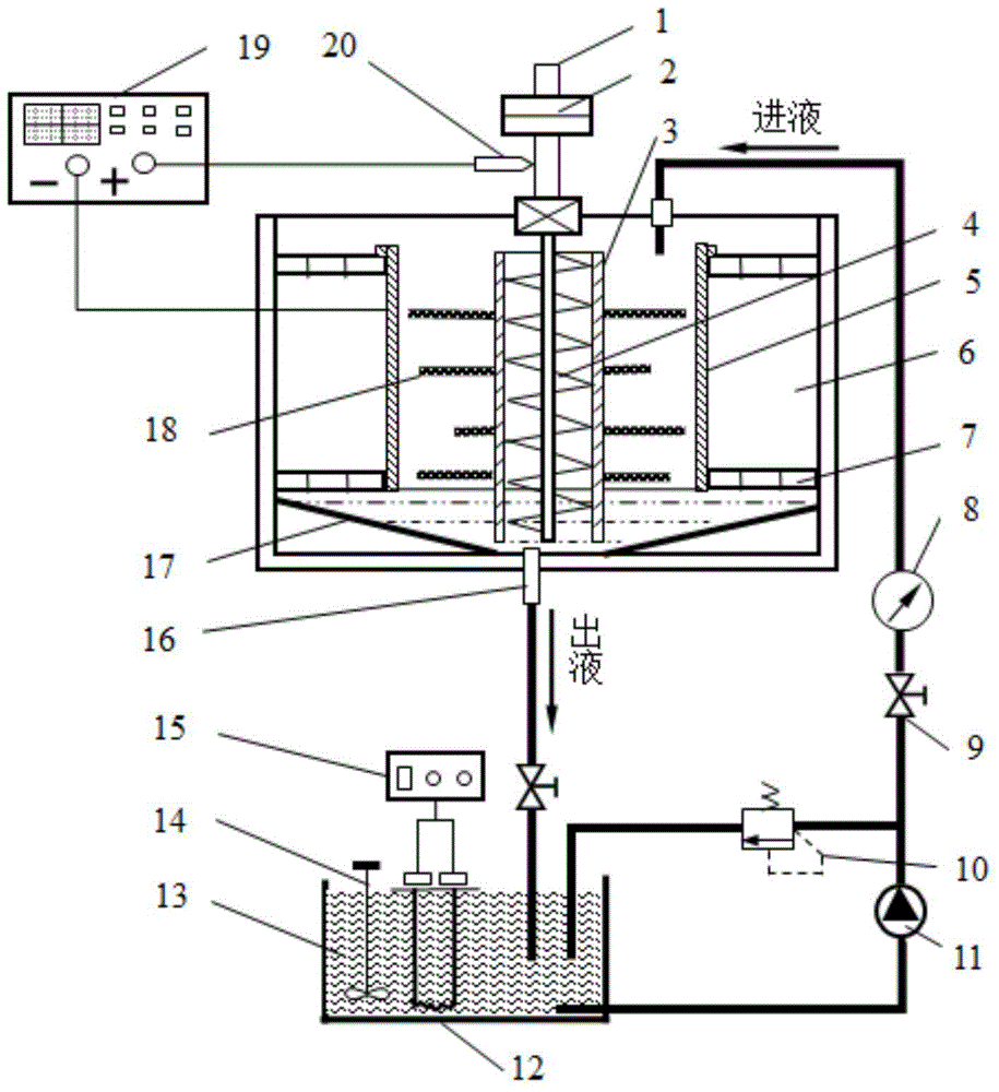
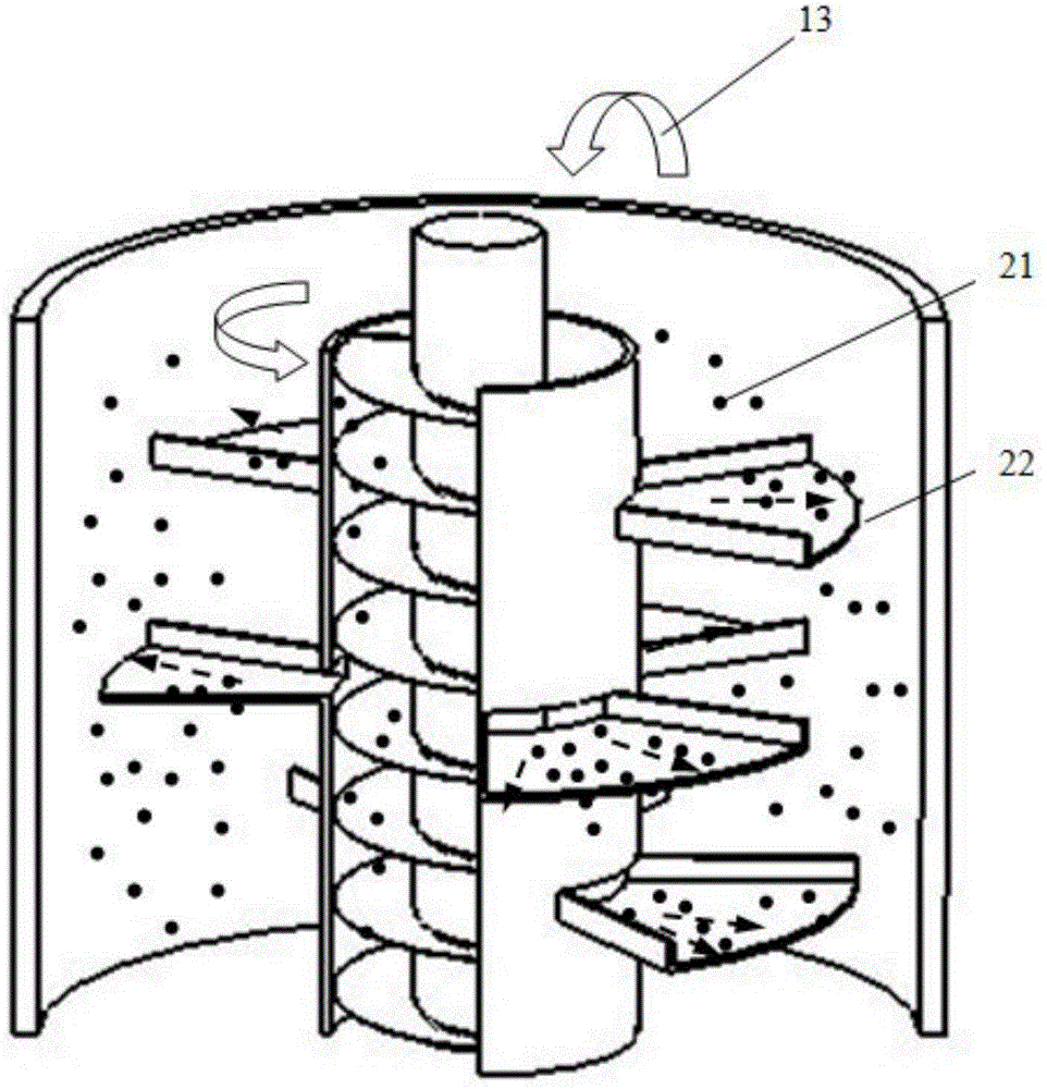
[0028] like figure 1 , figure 2 As shown, the centrifugal shot peening electroforming manufacturing device of the present invention is mainly composed of an electroforming tank 6, a centrifugal rotating system, an electrodeposition system and a solution circulation system; the solution circulation system includes a liquid storage tank 12, a magnetic pump 11. Ball valve 9, overflow valve 10, electroforming tank 6, collecting plate 17 and screw lifter 4, the inner wall of the electroforming tank 6 is provided with a bottom plate 7, and the collecting plate 17 is obliquely fixed on the bottom of the electroforming tank 6 A circulation pipeline is arranged between the liquid storage tank 12 and the electroforming tank 6, the magnetic pump 11, the pressure gauge 8, and the b...


PUM


Abstract

The invention provides a centrifugal shot blasting electroforming manufacturing method and device. Centrifugal force generated through rotation of a leaf disc is utilized for enabling an electroforming solution and spherical hard particles to be ejected and impact the surface of an electroforming core mold, accordingly, the reduction reaction is generated on the surface of the cathode of the electroforming core mold, a component with the needed shape is prepared in a deposition forming manner, and the electrochemical machining field in non-traditional machining is involved. Under the action of centrifugal force, the hard particles are thrown out together and hit the surface of the core mold, the rapid forming manufacturing of ejecting electro-deposition in the casting process is achieved, and the effect of the surface shot blasting strengthening processing is achieved. The rapid forming manufacturing and the surface shot blasting strengthening processing are synchronously combined, and therefore skin blister adsorption of the deposition and generation of accumulated protrusions can be effectively prevented; and the surface flatness and smoothness are improved, residual compressive stress can be generated for surface stamping, and the fatigue resisting strength of a casting layer is improved. The centrifugal shot blasting electroforming manufacturing method and device can be used for inner surface defect mending and performance intensifying of components, rapid preparing of functional materials and surface coating of cavity type components.

Description

technical field [0001] The invention belongs to the field of electrochemical manufacturing of special processing, in particular to a centrifugal shot peening electroforming manufacturing method and device. Background technique [0002] Electroforming manufacturing is a precision special processing method, which uses metal ions to undergo electrochemical reduction reaction on the surface of the cathode, and gradually deposits and shapes to realize the processing and manufacturing of parts. It has high replication accuracy and repeatability. Compared with other precision processing technologies, electroforming Casting also has the advantages of high precision and no cutting force. Therefore, electroforming manufacturing technology has been successfully applied to the manufacture and surface coating modification of various precision shaped and complex metal parts, such as: precision abrasive tools, electrical machining electrodes, aerospace mechanical components, etc. [0003]...

Claims


Application Information

Patent Timeline
IPC IPC(8): C25D1/00
Inventor 张朝阳姜雨佳聂昕庄鸿武黄磊陆海强刘皋郭晓杰
Owner JIANGSU UNIV
Learn More