
Laser-welding fiber grating surface temperature sensor and packaging method thereof

A fiber grating, laser welding technology, applied in the direction of thermometers, thermometers, instruments, etc. with physical/chemical changes, can solve the problems affecting the natural thermal expansion of metal substrates and fiber gratings, easy creep and aging, fiber grating center wavelength shift, etc. problems, to achieve the effect of improving long-term reliability and stability, overcoming creep and aging, and reducing contact thermal resistance

Inactive Publication Date: 2016-01-13
WUHAN UNIV OF TECH
View PDF7 Cites 9 Cited by
  • Summary
  • Abstract
  • Description
  • Claims
  • Application Information

AI Technical Summary

Problems solved by technology

There are many defects in the existing substrate-type fiber grating temperature sensor: (1) the fiber grating is fixed on the metal substrate by epoxy resin adhesive, and the epoxy resin adhesive is easy to creep and age during long-term work after curing, which will cause Causes the drift of the center wavelength of the fiber grating, which brings test errors and reduces the reliability of the long-term measurement of the fiber grating temperature sensor
The Chinese invention patent No. 201310017991.X "Fiber Bragg Grating High Sensitivity Temperature Sensor Based on Low Melting Point Glass Welding" uses low melting point glass welding to fix the fiber grating on the metal substrate, this method eliminates the problems of viscose creep and aging Influence, but glass welding is a kind of low melting point welding. When the working temperature of the sensor is high, the glass solder joint is easy to soften, which affects the reliability of the test, and the glass solder joint is brittle, easy to break, the sensor is easy to damage, and the reliability is poor; (2) The temperature field near the surface of the measured object often has a large temperature gradient in the normal direction. In the natural environment, the greater the temperature difference between the measured object and the ambient temperature (about 60 ° C, the experimental test value), the measured The larger the temperature gradient near the surface of the measured object (about -20°C / mm, experimental test value), the traditional substrate-type fiber grating temperature sensor is difficult to achieve accurate measurement of the surface temperature of the measured object in such a large temperature gradient; (3 ) The pigtails at both ends of the fiber grating are easily affected by external disturbances, and the disturbance of the external signal transmission fiber is easily transmitted to the fiber grating and the metal substrate, affecting the natural thermal expansion of the metal substrate and the fiber grating, resulting in greater interference and test errors
Therefore, the traditional substrate-type fiber grating temperature sensor is difficult to monitor the surface temperature of the object reliably for a long time, and it is urgent to design a packaging structure and corresponding packaging method of the fiber grating surface temperature sensor with high reliability.

Method used


Image

  • Laser-welding fiber grating surface temperature sensor and packaging method thereof
  • Laser-welding fiber grating surface temperature sensor and packaging method thereof
  • Laser-welding fiber grating surface temperature sensor and packaging method thereof

Examples


Embodiment Construction

[0029] The present invention will be further described below in conjunction with specific examples and accompanying drawings.

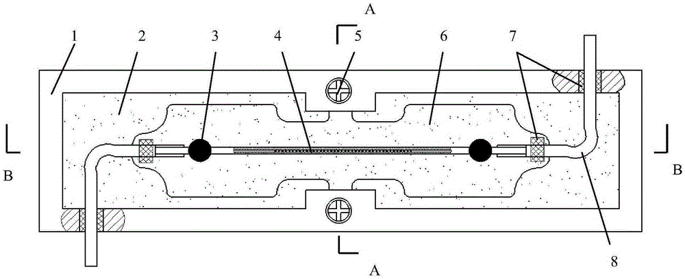
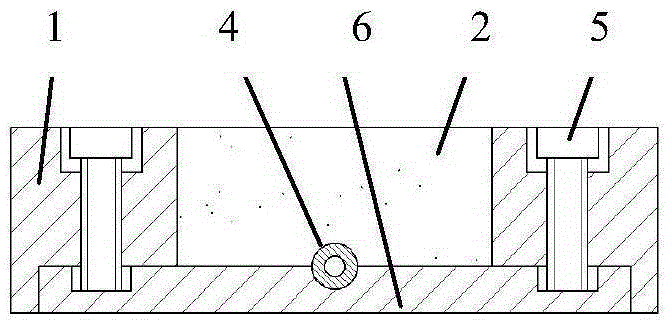
[0030] figure 1 It is a structural schematic diagram of an embodiment of the present invention, figure 2 for figure 1 A-A sectional view of, image 3 for figure 1 The B-B sectional view, Figure 4 for figure 1 The bottom view of a laser-welded fiber grating surface temperature sensor, comprising an optical fiber, a metal substrate 6 and a bottomless non-metallic frame 1; The signal transmission pigtail, the two ends of the fiber grating 4 coated with metal layer are fixed on the metal substrate 6 by laser welding, the signal transmission pigtail is covered with a protective fiber sleeve 8; the bottom of the non-metallic frame 1 and the metal The substrate 6 is fixed, and the non-metallic frame 1 is provided with a through hole for the fiber protection sleeve 8 to pass through, and the non-metallic frame 1 is filled with paste-like heat-conducti...


PUM


Abstract

The invention provides a laser-welding fiber grating surface temperature sensor which comprises a fiber, a metal substrate and a bottomless nonmetal framework. The fiber comprises a fiber grating plated with a metal layer and signal transmission tail fibers at the two sides of the fiber grating. The two ends of the fiber grating are fixed to the metal substrate through laser welding; the signal transmission tail fibers are respectively sleeved by a fiber protection sleeve pipe; the bottom portion of the nonmetal framework is fixed to the metal substrate; the nonmetal framework is provided with through holes for allowing the fiber protection sleeve pipes to pass through; and the nonmetal framework is internally filled with paste-like heat-conduction silicone grease. The fiber grating is subjected to coating layer removing and metal film layer plating, and is then, fixed to the metal substrate through the laser welding method, thereby realizing full metal packaging of a temperature sensing portion of the whole sensor, and overcoming creep and aging of adhesives in a conventional adhesive substrate fiber grating temperature sensor; and compared with glass welding, the laser-welding fiber grating surface temperature sensor has higher mechanical strength, and can bear higher test temperature; and fiber grating object surface temperature measurement long-term reliability and stability are improved on the whole.

Description

technical field [0001] The invention belongs to the field of optical fiber sensing, and in particular relates to a laser-welded optical fiber grating surface temperature sensor and a packaging method thereof. Background technique [0002] In many engineering applications and scientific research occasions, it is necessary to accurately measure the surface temperature of the object, such as the measurement of the inner surface temperature of the formed plastic mold, the measurement of the surface temperature of the key structural parts in the test of the aero-engine, the measurement of the surface temperature of the machine tool in the thermal error research of the CNC machine tool, etc. . The traditional object surface temperature measurement and sensing technologies are mainly sticky or gasket thermocouples, thermal resistance technology and non-contact infrared temperature measurement technology. Thermocouples and thermal resistances are electrical measurement technologies...

Claims


Application Information

Patent Timeline
IPC IPC(8): G01K11/00
Inventor 谭跃刚李瑞亚周祖德刘明尧黄晓
Owner WUHAN UNIV OF TECH
Learn More