
Vertical continuous electroplating hole filling line

A vertical continuous electroplating and hole line technology, applied in the direction of circuits, semiconductor devices, etc., can solve the problems of weak bonding between the coating and the substrate, uneven coating thickness, uneven appearance of filling holes, etc., and achieve compact structure and good thickness consistency , beautiful appearance effect

Pending Publication Date: 2017-05-10
DONGGUAN CRAY AUTOMATION TECH
View PDF0 Cites 2 Cited by
  • Summary
  • Abstract
  • Description
  • Claims
  • Application Information

AI Technical Summary

Problems solved by technology

When the hole depth of the non-through hole is deep or the thickness-to-diameter ratio is large, if horizontal electroplating is used, the non-through hole located on the lower surface of the high-density interconnection board is difficult to drive away the gas in the hole, and the plating solution is difficult to enter the hole. Therefore, the existing The problems of horizontal electroplating technology are: the appearance of the filling hole is uneven and meticulous, there are pits and pinholes, the thickness of the coating is uneven, the thickness of the coating on the hole wall is too different from the thickness of the coating on the board, and the coating is not combined with the substrate. Firmness and other bad phenomena

Method used


Image

  • Vertical continuous electroplating hole filling line
  • Vertical continuous electroplating hole filling line
  • Vertical continuous electroplating hole filling line

Examples


Embodiment Construction

[0029] The specific embodiment of the present invention will be further described below in conjunction with accompanying drawing:

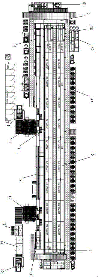
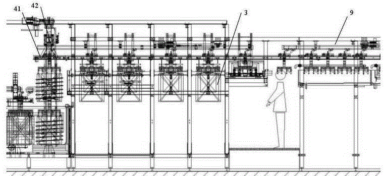
[0030] Such as figure 1 with figure 2 As shown, the vertical continuous electroplating filling line provided by the present invention includes several sub-lines arranged side by side. 5. Electroplating pretreatment device 58, several stages of electroplating copper cylinders 6, post-transfer device 7, post-processing device 8 and deplating device 9, this embodiment adopts two sub-lines of A line and B line arranged in parallel and the above-mentioned The devices are sequentially connected in a ring, obviously, the filling line can also be distributed in a linear or other form to the devices.

[0031] Such as image 3 with Figure 5 As shown, the pre-processing device 4 includes a feeding mechanism, an oil removal mechanism and a grading pre-processing mechanism. Synchronous operation, the feeding mechanism includes a guide post A2 and a guid...


PUM


Abstract

The present invention provides a vertical continuous electroplating hole filling line for PCB board processing. The vertical continuous electroplating hole filling line comprises a plurality of sub-lines arranged in a side-by-side manner, and is characterized in that each sub-line comprises a material feeding mechanism, a pretreatment device, a front shifting device, an electroplating pretreatment device, a multi-stage electroplating copper cylinder, a rear shifting device, a post-treatment device and a deplating device, wherein the material feeding mechanism, the pretreatment device, the front shifting device, the electroplating pretreatment device, the multi-stage electroplating copper cylinder, the rear shifting device, the post-treatment device and the deplating device are sequentially connected, the material inlet end of the material feeding mechanism is connected to an automatic plate feeding device, the material inlet end of the automatic plate feeding device is provided with a plate feeding conveying belt, and the material outlet end of the post-treatment device is sequentially connected to a central positioning machine, a corner turning machine, a horizontal plate drying machine and an automatic plate collection device. According to the present invention, with the vertical continuous electroplating hole filling line, the thickness uniformity of the plating layer at blind holes, buried holes and other hole filling positions of the high density circuit board, the deep plating ability, the hole filling ability and the bonding force are good, the shape is beautiful, the consistency of the hole wall plating layer and the plate surface plating layer is good, the operation, the maintenance and the repair are convenient, the structure is compact, the occupation space is small, the generated waste gas is less, and the environmental protection advantage is provided.

Description

technical field [0001] The invention relates to the electroplating technology of circuit boards, in particular to a vertical continuous electroplating hole filling line applied to high-density circuit boards / laminated multilayer boards. Background technique [0002] In the electroplating of high-density interconnection boards, in order to achieve high-density requirements, as the number of board layers continues to increase, the holes continue to shrink, and the thickness-to-diameter ratio of the holes is also increasing. At present, these micro-holes are generally smaller than 0.15 mm, or even smaller than 30-50 μm. Electroplating in such tiny holes with a high thickness-to-diameter ratio is quite different from the hole plating of conventional printed circuit boards. When the hole depth of the non-through hole is deep or the thickness-to-diameter ratio is large, if horizontal electroplating is used, the non-through hole located on the lower surface of the high-density inte...

Claims


Application Information

Patent Timeline
IPC IPC(8): C25D19/00C25D7/12
Inventor 邓志坚彭云韦万礼
Owner DONGGUAN CRAY AUTOMATION TECH
Learn More