

Integration reagent tube for luminescence immunodetection, and use method thereof
A technology of luminescent immunoassay and reagent tube, which is applied in the field of whole blood chemiluminescent immunoassay, can solve the problems of poor accuracy, repeatability, and low sensitivity, and achieve good repeatability, high sensitivity, and meet the effect of instant detection
- Summary
- Abstract
- Description
- Claims
- Application Information
AI Technical Summary
Problems solved by technology
Method used
Image

Examples
Embodiment 1
[0035] Embodiment one (The bottom surface of the microporous cup is integrally formed with a spherical segment as a reflector).
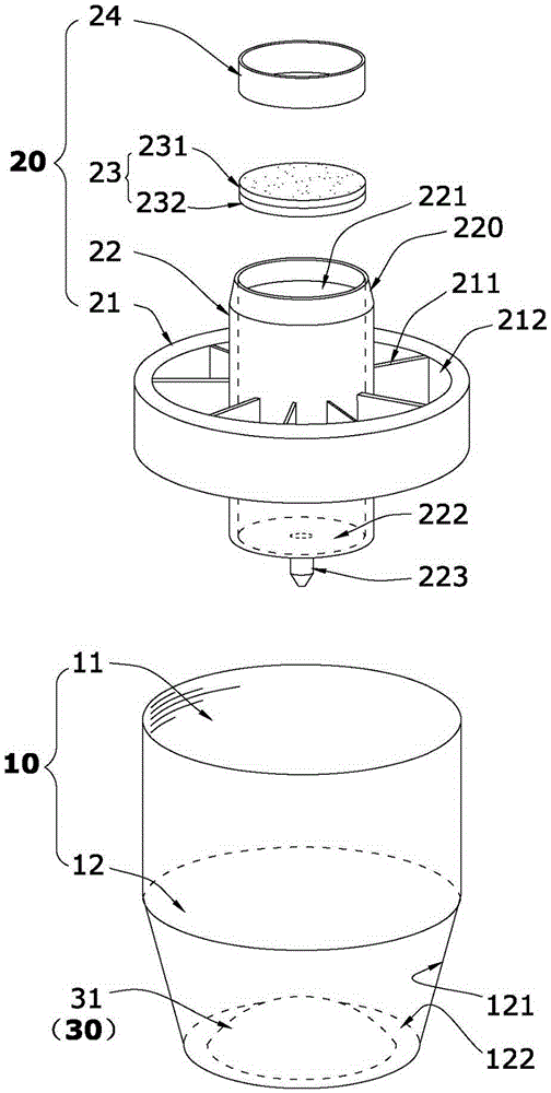
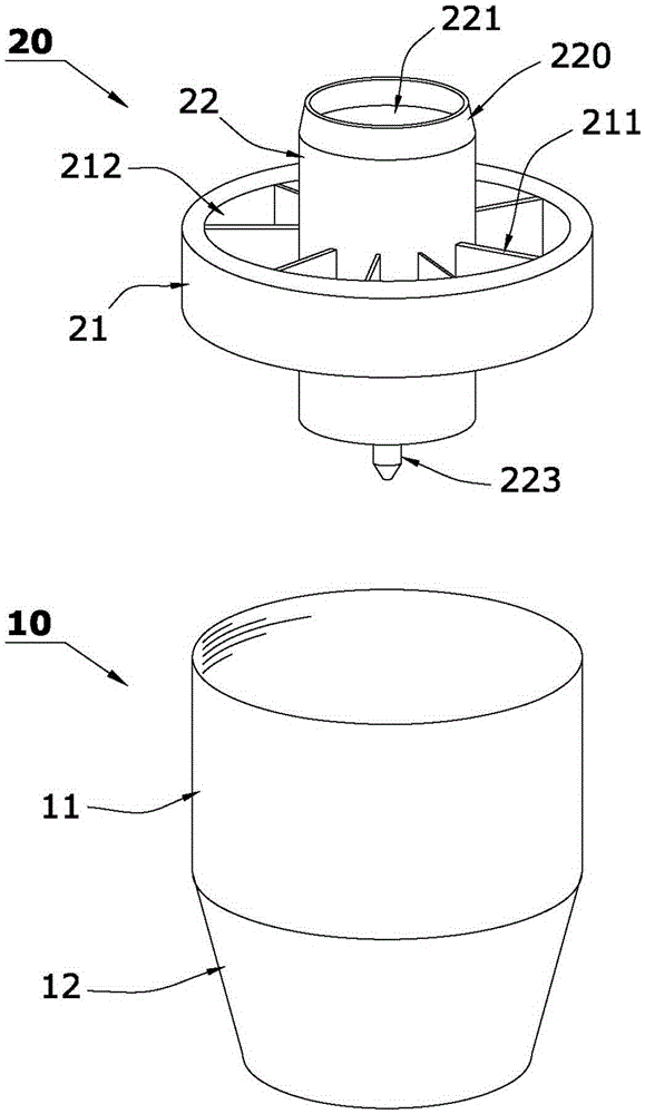
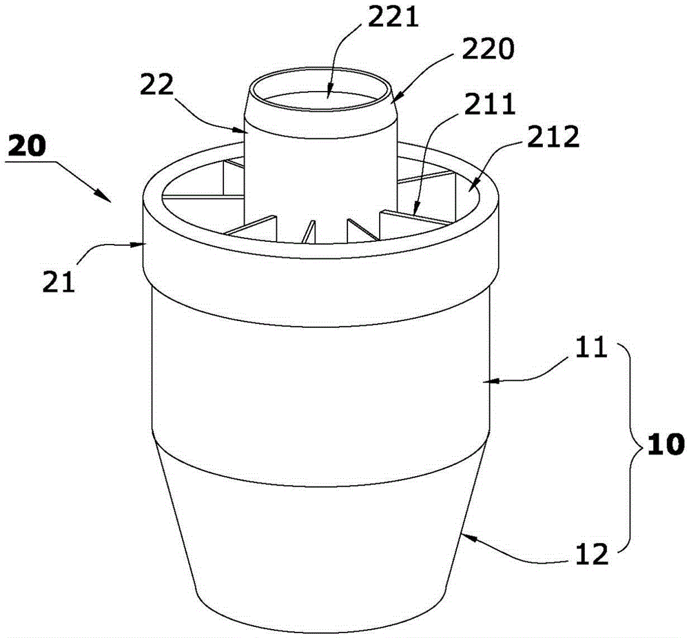
[0036] Such as Figure 1 to Figure 5 The shown integrated reagent tube for luminescence immunoassay includes a pre-solidified microporous cup 10 and a sample filter device 20 for filtering the liquid to be tested.
[0037] Such as figure 1As shown, the microporous cavity of the microporous cup 10 of the present invention is formed by connecting a round through hole 11 at the top and a cup hole 12 with a side ring wall 121 at the bottom to increase the upward projection and reflection focusing area. The cup of the present invention The hole is a cup hole 12 with a rounded table hole. The bottom surface 122 of the cup hole 12 is protrudingly provided with a reflector 30 that increases the upward projection and reflection focusing area, and a spherical segment 31 is used as a reflector (30 is integrated into the cup hole 12, the spherical segment 3...
Embodiment 2
[0048] Embodiment two (The integrally formed reflector on the bottom of the microporous cup can be replaced by other structures).
[0049] Such as Image 6 The difference between the shown integrated reagent tube for luminescence immunoassay and Example 1 is that the spherical segment 31 in Example 1 is replaced with one of cone 32, truncated cone 33, pyramid 34 or truncated prism 35; 32. The frustum 33, the pyramid 34 or the frustum 35 can increase the solid-liquid interface in the microhole cup 10, and the light on it can be reflected to the side wall of the cup hole 12 of the microhole cup 10 and converge after light detection. Make the photomultiplier tube (PMT) probe of the detection instrument receive more light signals from the solid-liquid interface; the sample filter device 20 of the integrated reagent tube for luminescent immunoassay in this embodiment is the same as that The method of using the integrated reagent tube for detection is the same as that in Example ...
Embodiment 3
[0050] Embodiment Three (Several tetrahedrons are integrally formed on the side ring wall 121 of the cup hole 12 of the microporous cup).
[0051] Such as Figure 7 As shown, the sample filtering device 20 of this embodiment is the same as that of Embodiment 1. A number of tetrahedrons 36 are integrally formed on the cup hole 12 side ring wall 121 of the microporous cup of this embodiment, and these tetrahedrons 36 increase the solid-liquid reaction Interface, and the solid-liquid reaction interface can be effectively irradiated by the projected light and reflected and converged, so that the light signal detected by the photomultiplier tube (PMT) probe of the detection instrument increases, and the detection sensitivity is greatly improved; the integrated reagent tube of this embodiment Using method is the same as embodiment one.
PUM
 Abstract
Description
Claims
Application Information