Large-mode-field ytterbium-doped optical fiber

A ytterbium-doped fiber, large mode field technology, applied in the direction of cladding fiber, multi-layer core/cladding fiber, optical waveguide light guide, etc. bad etc.

Inactive Publication Date: 2016-01-13
YANGTZE OPTICAL FIBRE & CABLE CO LTD
View PDF2 Cites 24 Cited by
  • Summary
  • Abstract
  • Description
  • Claims
  • Application Information

AI Technical Summary

Problems solved by technology

[0005] Among the above-mentioned optical fibers that can realize single-mode operation with large mode field area, the bending method is a relatively simple method to filter the mode, but this method is limited to small core diameter fibers. Once the core layer is large or the numerical aperture is low , the bending loss difference between the high-order mode and the base mode is reduced, and the energy leakage caused by the high-power filter mode will cause certain damage to the coating layer, which will seriously cause the coating layer to burn out
The core diameter is drastically reduced by the taper method, and it is easy to cause irreversible damage under high power, so it is difficult to filter out high-order modes by increasing the taper core diameter.
Others such as photonic crystal fiber, high-order mode fiber, and chiral coupling fiber can achieve excellent mode output and improve the quality of the output beam, but the preparation process of each fiber is relatively complicated, and the requirements for the process are extremely high. Large-scale commercial applications need more innovation

Method used


Image

  • Large-mode-field ytterbium-doped optical fiber
  • Large-mode-field ytterbium-doped optical fiber
  • Large-mode-field ytterbium-doped optical fiber

Examples


Embodiment 1

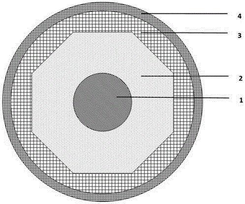
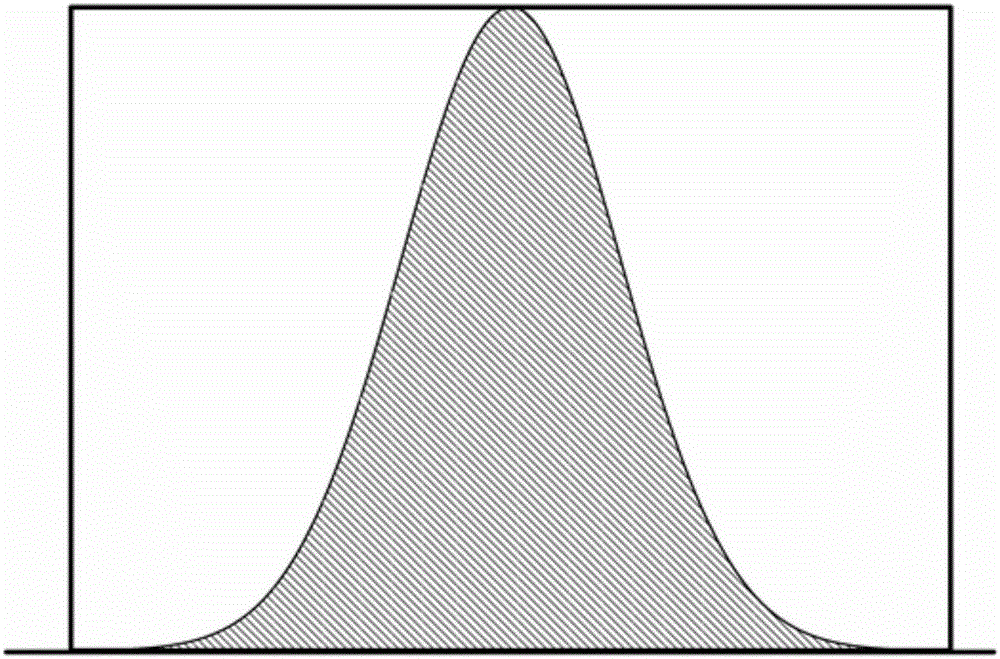
[0035] Example 1. During the test, the diameter of the fiber coil was kept fixed at 30cm: the core diameter was 20μm, the cladding diameter was 400μm, β=1, and the doping concentration of ytterbium in the core was nearly Gaussian. 2 o 3 The highest concentration calculated by mass fraction is 1000ppm, NA is 0.08, and the test results are processed by signal M 2 =1.2, the mode field diameter is 15um, the output power is 130W, and the slope efficiency is 70%. Test conditions: the output power of two 915nm LD pumps is 100W, and the central wavelength of the grating is 1060nm.

Embodiment 2

[0037] Example 2. During the test, the fiber coil diameter was kept fixed at 30cm: the core diameter was 30μm, the cladding diameter was 400μm, β=0.9, and the doping concentration of ytterbium in the core was Gaussian. 2 o 3 The highest concentration that mass fraction calculates is 1000ppm, and NA is 0.06, and other test conditions are identical with embodiment 1, and test result is through signal processing M 2 =1.3, the mode field diameter is 23um, the output power is 132W, and the slope efficiency is 71%.

Embodiment 3

[0039] Example 3. During the test, the diameter of the fiber coil was kept fixed at 30cm: the core diameter was 35μm, the cladding diameter was 400μm, β=1.1, and the doping concentration of ytterbium in the core was Gaussian. 2 o 3 The highest concentration that mass fraction calculates is 1000ppm, and NA is 0.06, and other test conditions are identical with embodiment 1, and test result is through signal processing M 2 =1.5, the mode field diameter is 29um, the output power is 134W, and the slope efficiency is 72%.


PUM


Abstract

The invention discloses a large-mode-field ytterbium-doped optical fiber. The optical fiber is provided with a core layer containing ytterbium at least, a glass substrate internal wrapping layer which surrounds the core layer, and a low-refractive-index coating layer which surrounds the glass substrate wrapping layer. Ytterbium concentration of the center of the optical fiber along any diameter direction of the core layer is the highest, and ytterbium concentration gradually reduces from the center to the two end points. Distribution of ytterbium concentration of the core layer along the diameter direction of the core layer meets Gaussian distribution. The optimized optical fiber output light beam quality is acquired by the design without reducing core layer doping concentration or changing bending property or increasing optical fiber preparation difficulty.

Description

technical field [0001] The invention belongs to the field of optical fiber technology, and more specifically relates to a large mode field ytterbium-doped optical fiber. Background technique [0002] When pump light of a certain wavelength is injected into the optical fiber doped with rare earth elements in the core layer, the population inversion will be formed, and stimulated emission will be formed. Therefore, the rare earth-doped fiber is used in the fiber amplifier to amplify the signal light of stimulated radiation, and in the fiber laser, the light of stimulated radiation can be amplified to have exactly the same properties as the signal light due to the function of the resonant cavity. The doping of different rare earth elements can radiate light of different wavelengths under the excitation of corresponding wavelengths, and can cover a large spectral range. [0003] Among them doped with ytterbium (Yb 3+ ) optical fiber is a kind of rare earth doped optical fiber....

Claims


Application Information

Patent Timeline
Patent Type & Authority Applications(China)
IPC IPC(8): H01S3/067G02B6/02G02B6/036
Inventor 杨玉诚曹蓓蓓陈苏韦会峰汪洪海
Owner YANGTZE OPTICAL FIBRE & CABLE CO LTD
Why Eureka
Try Eureka