Equipment and process for condensing and collecting steam and waste gas at tail end of multi-grade flash evaporation device

A flash evaporation device and steam technology, which can be used in steam condensation, chemical instruments and methods, and dispersed particle separation, etc., can solve problems such as air pollution and harm the environment, and achieve the effect of protecting the environment and avoiding air pollution.

Inactive Publication Date: 2016-01-20
山东丰特环保科技有限公司
7 Cites 5 Cited by

AI-Extracted Technical Summary

Problems solved by technology

The used cooling water enters the cooling tower for cooling. During the cooling process of the cooling tower, the H in the water 2 S, ...

Abstract

The invention relates to equipment and a process for condensing and collecting steam and waste gas at the tail end of a multi-grade flash evaporation device and belongs to the technical field of production of viscose. The equipment comprises the multi-grade flash evaporation device, wherein the tail end of the multi-grade flash evaporation device is connected with a primary indirect condenser and a secondary condenser; the primary indirect condenser and the secondary condenser are connected through a pipeline; the secondary condenser is connected with a steam injection pump and a tertiary condenser through a pipeline in sequence; the steam injection pump is connected with a steam source; and the tertiary condenser is connected with a vacuum pump and a waste gas treatment system through a pipeline in sequence. The process can be used for completely collecting uncondensed waste gas generated by multi-grade flash evaporation so that all toxic waste gas generated by the multi-grade flash evaporation enters the waste gas treatment system, and furthermore, the air pollution is avoided and the environment is protected.

Application Domain

Technology Topic

EngineeringToxic waste +7

Image

  • Equipment and process for condensing and collecting steam and waste gas at tail end of multi-grade flash evaporation device

Examples

  • Experimental program(1)

Example Embodiment

[0016] The embodiments of the present invention will be further described below in conjunction with the accompanying drawings:
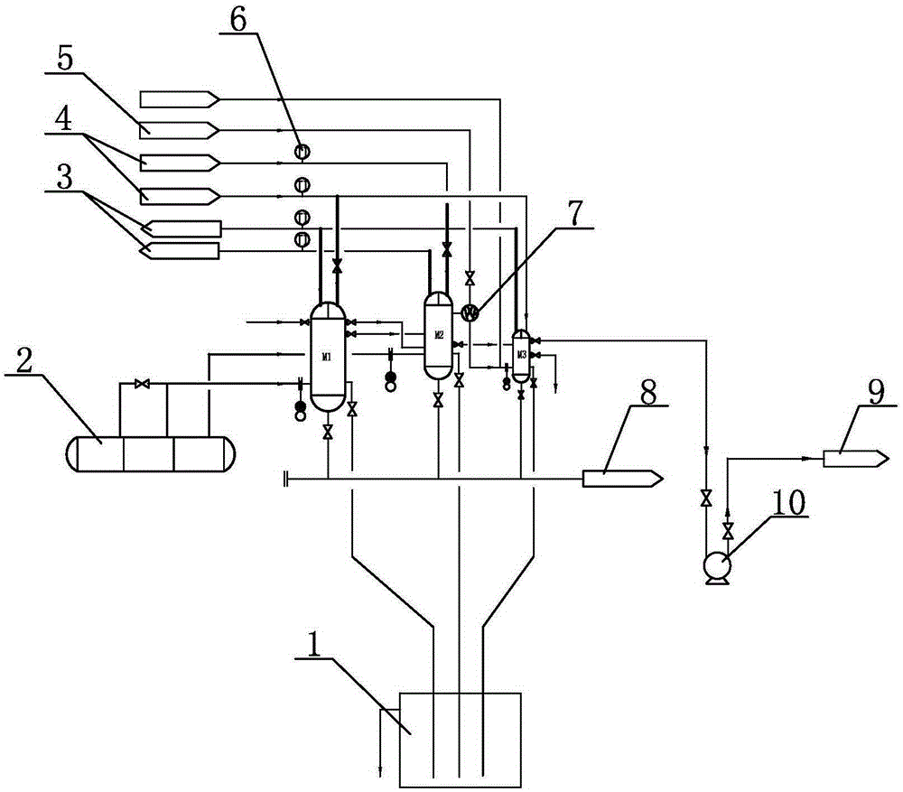
[0017] Such as figure 1 As shown, the equipment for condensing and collecting the steam and waste gas at the end of the multi-stage flash vaporization device includes a multi-stage flash vaporization device 2. The end of the multi-stage flash vaporization device 2 is connected to a primary indirect condenser M1 and a secondary condenser M2 through pipelines, The first-stage indirect condenser M1 and the second-stage condenser M2 are connected by pipelines, the second-stage condenser M2 is connected to the steam jet pump 7 and the third-stage condenser M3 through the pipelines, the steam jet pump 7 is connected to the steam source 5, and the third-stage condensation The device M3 is connected to the vacuum pump 10 and the exhaust gas treatment system 9 in turn through pipelines;
[0018] The first-stage indirect condenser M1, the second-stage condenser M2 and the third-stage condenser M3 are all connected to the liquid-sealed barrel 1 through pipes, and the heat exchange tube inlets of the first-stage indirect condenser M1, the second-stage condenser M2 and the third-stage condenser M3 Both the outlet and the outlet are respectively connected to the cooling water source 4 and the sink 5 through pipelines. The heat exchange tubes of the first-stage indirect condenser M1, the second-stage condenser M2 and the third-stage condenser M3 are all emptied of the return tank 8 through the pipeline connection pipe. .
[0019] The condenser includes a shell and a heat exchange tube located in the shell. The three-stage condensation device can be formed by a group of condensers or multiple groups of condensers in parallel. The cooling water enters the heat exchange tube through the pipeline, and then returns to the sink 3 to form a complete loop. When not in use, it can be drained to the tube side to empty the return sink 8.
[0020] The pipeline between the inlet of the heat exchange tube of the first-level indirect condenser M1, the second-level condenser M2 and the third-level condenser M3 and the cooling water source 4 is equipped with a temperature measuring device 6, the first-level indirect condenser M1, and the second-level condenser There is a temperature measuring device 6 on the pipeline between the heat exchange tube outlet of the M2 and the three-stage condenser M3 and the sink 5. According to the temperature measuring device 6 through the valve, the flow of cooling water is adjusted in real time to control the water temperature and meet the process parameters need.
[0021] A cleaning pipeline is communicated between the first-stage indirect condenser M1, the second-stage condenser M2, and the third-stage condenser M3.
[0022] The front end of the multi-stage flashing device 2 is connected to a three-stage condenser M3 through a pipeline.
[0023] The 14-stage flash evaporation device is currently the world’s most mature and advanced device in the acid bath evaporation process of the viscose fiber industry. The terminal secondary steam of the 14-stage flash evaporation device contains H 2 S and CS 2 Gas, the process of collecting steam and waste gas at the end of the multi-stage flash evaporation device using the condensation of the above-mentioned equipment. The specific process is as follows: the low-temperature acidic steam and toxic and odorous waste gas at the end of the multi-stage flash evaporation device 2 are divided into two parts, one part of the gas temperature At about 44℃, it enters the shell of the first-stage indirect condenser M1 through the pipeline, and exchanges heat with the heat exchange tube with cooling water. After cooling down, the acid vapor in this part of the gas is condensed into condensate. Transported to liquid sealed barrel 1 through pipeline, non-condensable H 2 S and CS 2 The exhaust gas enters the secondary condenser M2 through the pipeline; the temperature of another part of the gas is about 34°C, enters the shell of the secondary condenser M2 through the pipeline, and exchanges heat with the heat exchange tube passing through the cooling water. The acidic vapor is condensed into condensate, and the condensate is transported to the liquid-sealed barrel 1 through the pipeline, and the non-condensable H in the secondary condenser M2 2 S and CS 2 The exhaust gas, including the non-condensable exhaust gas delivered by the first-stage indirect condenser M1, is sent to the third-stage condenser M3 shell by the steam jet pump 7, and further exchanges heat with the heat exchange tube through which cooling water is passed. The condensed gas is condensed, and the condensate is transported to the liquid-sealed barrel 1 through the pipeline. The final non-condensable exhaust gas is discharged from the three-stage condenser M3 to the exhaust gas treatment system 9 through the vacuum pump 10; the second front end of the multi-stage flashing device 2 The final non-condensable gas of the secondary steam also enters the three-stage condenser M3 through the pipeline for final condensation, and finally enters the vacuum pump 10 and is discharged to the exhaust gas treatment system 9.
[0024] The entire process is completed under negative pressure. The negative pressure of the equipment and the entire multi-stage flashing device is realized by the steam jet pump 7 connected to the two-stage condenser M2 and the vacuum pump 10 connected to the three-stage condenser M3 , And the vacuum degree of the secondary condenser M2 is higher than that of the primary indirect condenser M1.
[0025] When cleaning is required, the alkaline cleaning liquid enters the first-stage indirect condenser M1, the second-stage condenser M2, and the third-stage condenser M3 through the pipeline, and finally completes the cleaning cycle, and the cleaning liquid is discharged into the recovery tank.

PUM

no PUM

Description & Claims & Application Information

We can also present the details of the Description, Claims and Application information to help users get a comprehensive understanding of the technical details of the patent, such as background art, summary of invention, brief description of drawings, description of embodiments, and other original content. On the other hand, users can also determine the specific scope of protection of the technology through the list of claims; as well as understand the changes in the life cycle of the technology with the presentation of the patent timeline. Login to view more.

Similar technology patents

Watersoluble packaging pouch printing ink and method for preparing the same

ActiveCN101492583AAvoid air pollutionImprove printing environmentInksWaxFire hazard
Owner:广东佳景科技股份有限公司

Negative pressure boiler for air sterilization

Owner:天津有序环境科技发展有限公司

Classification and recommendation of technical efficacy words

  • Protect environment
  • Avoid air pollution

Method for recovering rare earth from waste rare earth luminescent material

InactiveCN102660688AHigh recovery rateProtect environmentGlass recyclingCerium oxides/hydroxidesRare-earth elementGlass matrix
Owner:UNIV OF SCI & TECH BEIJING

Environmental protective covering for electrical power connectors

InactiveUS7771221B1Efficient cable routingProtect environmentCouplings bases/casesEngineeringAll terrain vehicles
Owner:BLACKWELL DONALD A
Why Eureka
Try Eureka