Machining method for aero-engine high-temperature alloy counterweight blade

An aero-engine and high-temperature alloy technology, which is applied in the processing field of aero-engine high-temperature alloy counterweight blades, can solve problems such as low processing efficiency, poor consistency, and inconsistent processing standards, so as to improve processing efficiency, reduce the number of tooling, and shorten the processing time. cycle effect

Active Publication Date: 2016-01-20
JIANGSU JITRI HUST INTELLIGENT EQUIP TECH CO LTD
View PDF6 Cites 14 Cited by
  • Summary
  • Abstract
  • Description
  • Claims
  • Application Information

AI Technical Summary

Problems solved by technology

Its disadvantages are: first, the blade root and the leaf body are processed twice, the processing standard is not uniform, the consistency is poor, the processing accuracy is difficult to guarantee and manual re-clamping is required, and the processing efficiency is low; Two sets of tooling, and the second step requires high precision of the tongue and groove profiling jig, resulting in higher cost of tooling

Method used


Image

  • Machining method for aero-engine high-temperature alloy counterweight blade
  • Machining method for aero-engine high-temperature alloy counterweight blade
  • Machining method for aero-engine high-temperature alloy counterweight blade

Examples


Embodiment Construction

[0029] The technical solutions of the present invention will be further described below in conjunction with the accompanying drawings and through specific implementation methods.

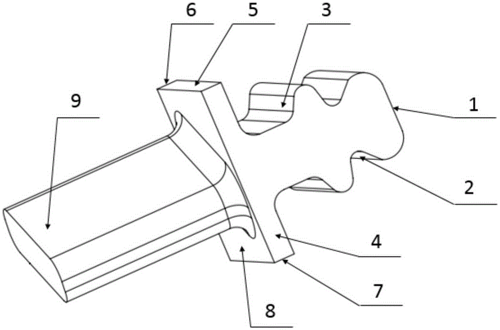
[0030] see Figure 1 to Figure 5 As shown, in this embodiment, a method for processing a superalloy counterweight blade of an aero-engine, the counterweight blade is composed of a blade root and a blade profile 9, wherein the blade root includes: a blade root end surface 1, a steam inlet edge mortise 2 , steam outlet side mortise 3, inner arc radial surface 4, steam outlet side 5, back arc radial surface 6, steam inlet side 7, and the transition surface 8 between the blade shape and the blade root; the blank of the counterweight blade is Enveloping the block blank 9 of the blade root and the blade shape, the specific processing method of the counterweight blade is as follows:

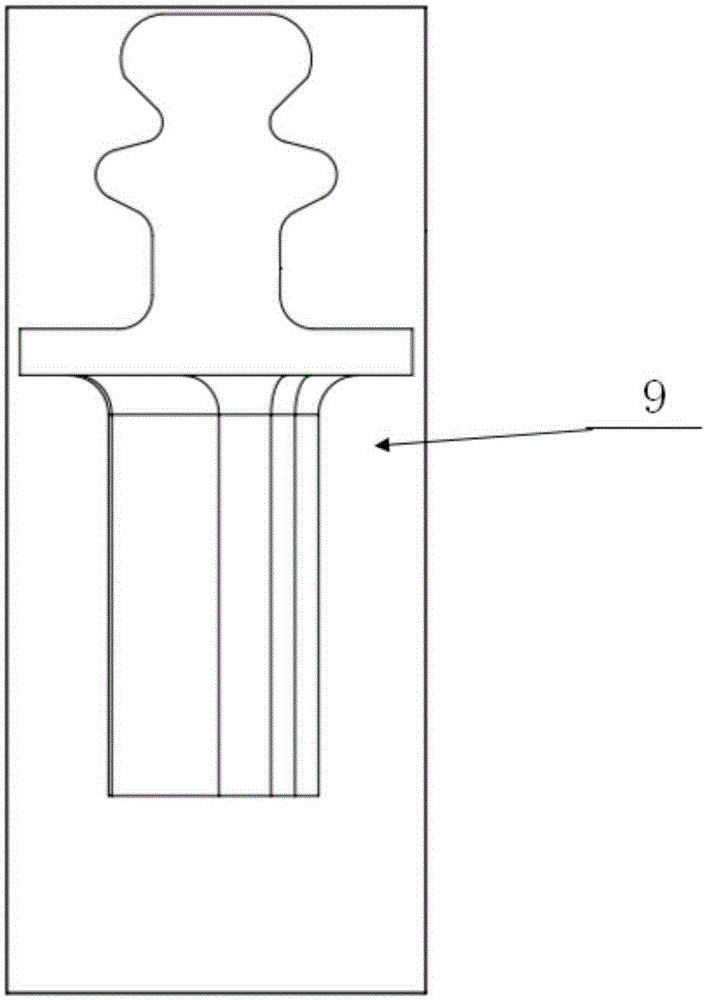
[0031] 1. Wire cutting blade root tenon and groove: such as image 3 As shown, most of the margin of the tongue and groov...


PUM


Abstract

The invention discloses a machining method for an aero-engine high-temperature alloy counterweight blade. The machining method includes the following steps that (1) a blade root mortise is cut in a wire cutting mode, specifically, most of the margin of a mortise part of a counterweight blade blank is removed through a wire cutting method; (2) the blade root and the blade form are milled, specifically, the blade root of the blank with the mortise margin removed in a wire cutting mode is upwards vertically clamped on a two-rotary-table five-shaft linkage machining center, then the end surface, the inner arc radial surface, the back arc radial surface, the steam inlet lateral surface and the steam outlet lateral surface of the blade root are machined through a face mill cutter in a rough and fine mode, a profile modeling milling cutter is used for machining a mortise in the steam inlet side and a mortise in the steam outlet side, and finally the adaptation surface of the blade root and the blade form and a blade form surface are machined in a rough, semi-fine and fine mode; and (3) the blade crown is cut in a wire cutting mode. According to the machining method for the aero-engine high-temperature alloy counterweight blade, the clamping frequency, the tool number and the varieties of tools are reduced. Meanwhile, the machining procedure is reasonably planned, reliability of machining is guaranteed, the machining accuracy is guaranteed, the machining efficiency is improved, and the production cost is reduced.

Description

technical field [0001] The invention belongs to the processing technology of aero-engine blades, in particular to a processing method of an aero-engine superalloy counterweight blade. Background technique [0002] The counterweight blades in the aero-engine balance the weight distribution of the entire rotating parts during the operation of the engine, so that the engine can reach a state of static and dynamic balance. The processing object in the present invention is the turbine disk counterweight blade, which must be able to work stably under the conditions of high temperature, high pressure and high speed, so it is required to be able to withstand high temperature, and the assembly with the transmission shaft must be accurate and reliable, so the turbine counterweight The material of the blade is generally a high-temperature alloy, and the machining accuracy and surface quality requirements of the tenon area are particularly high. The difficult-to-machinability and high p...

Claims


Application Information

Patent Timeline
Patent Type & Authority Applications(China)
IPC IPC(8): B23P15/02
CPCB23P15/02
Inventor 代星唐祥武鄢龙志严思杰丁汉岳晶崔光玉李斌
Owner JIANGSU JITRI HUST INTELLIGENT EQUIP TECH CO LTD
Why Eureka
Try Eureka