Sludge splitting and gasifying method

A technology of sludge cracking and cracking gas, which is applied in the field of sludge treatment, can solve the problems of difficult secondary pollution control of flue gas, low degree of sludge resource utilization, etc., to avoid corrosion of equipment, high cracking efficiency, and fast reaction rate Effect

Active Publication Date: 2016-01-20
SHANGHAI MUNICIPAL ENG DESIGN INST GRP
View PDF11 Cites 0 Cited by
  • Summary
  • Abstract
  • Description
  • Claims
  • Application Information

AI Technical Summary

Problems solved by technology

[0005] The purpose of the present invention is to provide a method for sludge treatment to solve the problems of low sludge resource utilization and difficult secondary pollution

Method used


Image

  • Sludge splitting and gasifying method
  • Sludge splitting and gasifying method

Examples


Embodiment 1

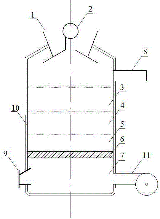
[0043] The sludge cracking and gasification device is provided with a shell 10 on the outside, a sludge feed port 1 is provided on the top of the shell 10, and a drying chamber 3, a pyrolysis chamber 4, an oxidation Room 5 and Ash Room 7.

[0044]The shell 10 is in the shape of an upright barrel, the inner wall of the shell 10 is made of steel plate lined with refractory bricks or refractory cement, and the surface is covered with thermal insulation materials. The sludge feed port 1 is provided with a feed valve 2; the sludge feed port 1 is funnel-shaped, and is closely matched with the feed valve 2 to form a seal to prevent cracking gas from escaping. The upper part of the drying chamber 3 is provided with a pyrolysis gas outlet pipe 8 . The side wall of the ash chamber 7 is provided with a slag outlet 9 and a gasification medium introduction pipe 11 . A grate 6 is arranged between the oxidation chamber 5 and the ash chamber 7 . The grate 6 is made of refractory material, ...


PUM


Abstract

The invention discloses a sludge splitting and gasifying method. The sludge is treated through a sludge splitting and gasifying device. The device comprises a shell, a sludge feed inlet formed in the top part of the shell, and a drying chamber, a pyrolysis chamber, an oxidizing chamber and an ash residue chamber downwards and sequentially arranged from the sludge feed inlet in the shell, wherein a pyrolysis gas eduction tube is arranged on the upper part of the drying chamber; a furnace bar is arranged between the oxidizing chamber and the ash residue chamber, and is made of refractory matters; a plurality of oblique cylinder shaped holes are formed in the furnace bar; a slag discharge hole and a gasifying medium introduction pipe are arranged on the side wall of the ash residue chamber; the shell is in an upright barrel shape; an inlet valve is arranged on the sludge feed inlet; the sludge feed inlet is in a funnel shape; the sludge feed inlet and the inlet valve are closely identical to form seal. The sludge splitting and gasifying method provided by the invention is used for treating the sludge, has the characteristics that the gasifying efficiency is high, the pollutant generation is avoided on the source, and can realize reduction, stabilization, harmlessness and resource recovery of the sludge without additionally adding energy.

Description

technical field [0001] The invention relates to a sludge treatment method in environmental protection technology, in particular to a sludge cracking and gasification method. Background technique [0002] With the rapid development of urban sewage treatment in my country, the number of sewage treatment plants is increasing, and the amount of sludge generated is also increasing. According to statistics, at present, the annual sludge production of urban sewage treatment plants in my country has reached 30 million tons (water content 80%), and will reach about 50 million tons by the end of the "Twelfth Five-Year Plan". [0003] Sludge incineration treatment and disposal is an important means to achieve sludge reduction, stabilization and harmlessness. However, the direct incineration of sludge has the problems of low combustion efficiency and single energy utilization mode; in addition, the flue gas of sludge incineration contains PM2.5, NO x , SO 2 And dioxin and other pollu...

Claims


Application Information

Patent Timeline
IPC IPC(8): C10J3/02C10J3/20C10J3/74C10J3/30C10J3/36C10J3/66C10J3/82
Inventor 张辰邹伟国王磊向阳谭学军王逸贤
Owner SHANGHAI MUNICIPAL ENG DESIGN INST GRP
Why Eureka
Try Eureka