

Novel quantum dot luminescent device
A new type of quantum dot light-emitting technology, applied in the fields of electric solid-state devices, semiconductor devices, semiconductor/solid-state device manufacturing, etc., can solve the problems of unbalanced electron and hole injection, low external quantum efficiency, etc., to improve the luminescence performance, repeatability Good performance, repeatable stability
- Summary
- Abstract
- Description
- Claims
- Application Information
AI Technical Summary
Problems solved by technology
Method used
Image

Examples
Embodiment 1
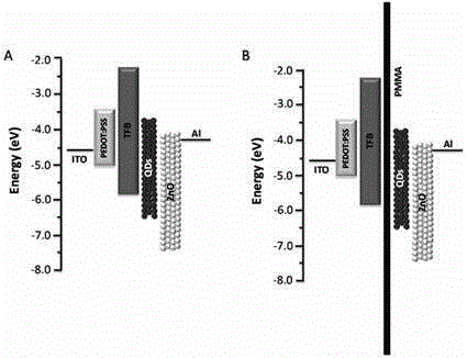
[0032] A new type of quantum dot light-emitting device, including ITO anode, hole injection layer (HILs), hole transport layer (HTLs), quantum dot light-emitting layer (QDs), electron transport layer (ETLs) and Al cathode, which also includes an insulating layer, the insulating layer is arranged between the hole transport layer and the quantum dot light-emitting layer. Its structural energy level diagram is shown in figure 1 .. Specifically obtained through the following steps:
[0033] Use the ITO glass of the cleaned pattern painting with an ultraviolet-ozone treatment machine (UV / O 3 ) for 15 minutes, and then spin-coat a 40nm PEDOT:PSS film on an ITO glass substrate at a speed of 3000 rpm as a hole injection layer by spin coating. The ITO glass substrate with spin-coated PEDOT:PSS thin film was dried in air at 150° C. for 15 min, then transferred to a glove box and spin-coated with a concentration of 10 mg / mL TFB chlorobenzene solution 30 nm as a hole transport layer, a...
Embodiment 2
[0036]A new type of quantum dot light-emitting device, including ITO anode, hole injection layer (HILs), hole transport layer (HTLs), quantum dot light-emitting layer (QDs), electron transport layer (ETLs) and Al cathode, which also includes an insulating layer, the insulating layer is arranged between the hole transport layer and the quantum dot light-emitting layer. Specifically obtained through the following steps:
[0037] Use the ITO glass of the cleaned pattern painting with an ultraviolet-ozone treatment machine (UV / O 3 ) for 15 minutes, and then spin-coat a 40nm PEDOT:PSS film on an ITO glass substrate at a speed of 3000 rpm as a hole injection layer by spin coating. The ITO glass substrate with spin-coated PEDOT:PSS thin film was dried in air at 150° C. for 15 min, then transferred to a glove box and spin-coated with a concentration of 10 mg / mL TFB chlorobenzene solution 30 nm as a hole transport layer, and Dry in a glove box at 150°C for 30 min. Continue to spin-c...
Embodiment 3
[0040] A new type of quantum dot light-emitting device, including ITO anode, hole injection layer (HILs), hole transport layer (HTLs), quantum dot light-emitting layer (QDs), electron transport layer (ETLs) and Al cathode, which also includes an insulating layer, the insulating layer is arranged between the hole transport layer and the quantum dot light-emitting layer. Specifically obtained through the following steps:
[0041] Use the ITO glass of the cleaned pattern painting with an ultraviolet-ozone treatment machine (UV / O 3 ) for 15 minutes, and then spin-coat a 40nm PEDOT:PSS film on an ITO glass substrate at a speed of 3000 rpm as a hole injection layer by spin coating. The ITO glass substrate with spin-coated PEDOT:PSS thin film was dried in air at 150° C. for 15 min, then transferred to a glove box and spin-coated with a concentration of 10 mg / mL TFB chlorobenzene solution 30 nm as a hole transport layer, and Dry in a glove box at 150°C for 30 min. Continue to spin-...
PUM
| Property | Measurement | Unit |
|---|---|---|
| Bandgap width | aaaaa | aaaaa |
| Thickness | aaaaa | aaaaa |
Abstract
Description
Claims
Application Information