Ultrasonic vibration auxiliary micro-electrochemical electrical discharge wire-cutting machining method and device

An ultrasonic vibration and EDM wire technology, which is applied in the field of composite micromachining, can solve the problems of high-precision machining of structures that cannot have a depth-to-width ratio, mechanical stress and thermal stress, and difficulty in discharging wear debris, so as to improve machining efficiency, increase The effect of large maximum length and increased thickness

Inactive Publication Date: 2016-01-27
SHANDONG UNIV
View PDF5 Cites 11 Cited by
  • Summary
  • Abstract
  • Description
  • Claims
  • Application Information

AI Technical Summary

Problems solved by technology

This method cannot process high-precision structures with deep aspect ratios, because the grinding debris is difficult to discharge, and it may also cause mechanical and thermal stress; The action will cause the crack to grow

Method used


Image

  • Ultrasonic vibration auxiliary micro-electrochemical electrical discharge wire-cutting machining method and device

Examples


Embodiment 1

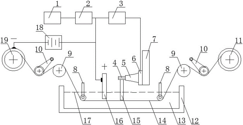
[0020] Such as figure 1 As shown, the ultrasonic vibration-assisted micro-electrolytic wire electric discharge processing method and device of the present invention mainly include an electrolysis-wire electric discharge device, an ultrasonic vibration unit and a workbench. Under the control of the control computer 1, the ultrasonic power supply 3 sends out an ultrasonic signal, which is converted into a mechanical vibration signal by the ultrasonic transducer 6, amplified by the horn 5 and transmitted to the workpiece 15 through the clamping device 4, so that the workpiece 15 Vibrate along the axial direction of the electrode wire 14; the horn 5 and the clamping device 4, and between the clamping device 4 and the workpiece 15 are fixedly connected by threads; the spindle 7 drives the workpiece 15 to perform feed motion (including Y and Z direction of feed), the feed speed is controlled by the control computer 1; the driving wheel 11 drives the electrode wire 14 out of the wire...

Embodiment 2

[0022] Such as figure 1 As shown, the electrolysis-electric spark power supply 18 adopts a DC pulse power supply, the electrolyte solution 13 adopts a sodium hydroxide solution, and the others are as in Example 1.

Embodiment 3

[0024] Such as Figure 1 As shown, the electrode wire 14 is made of steel wire, the horn 5 and the clamping device 4 , and the clamping device 4 and the workpiece 15 are all fixedly connected by bonding, and others are as in Example 1.

[0025]The invention is oriented to the micromachining of non-conductive hard and brittle materials, and has a good processing effect on high-aspect-ratio microstructure parts, and uses ultrasonic vibration to assist electrolysis-EDM. Since the workpiece is ultrasonically vibrated along the direction of the electrode wire, the electrolyte is accelerated. Renewal and chip removal can ensure machining accuracy and machining stability, and improve machining efficiency.


PUM


Abstract

The invention belongs to the field of combined micro-machining and relates to an ultrasonic vibration auxiliary micro-electrochemical electrical discharge wire-cutting machining method and device for non-conductive hard and brittle material machining. The machining method comprises the steps that ultrasonic vibration is utilized for exciting a workpiece in the axial direction of an electrode wire, the electrode wire and an auxiliary electrode are subjected to an electrolytic reaction in an electrolytic solution so that hydrogen gas is separated out around the electrode wire, and then a gas film is formed so that the electrode wire and the electrolytic solution can be insulated. The machining device comprises a machine tool bed, an electrolysis-electrical discharge wire cutting device, an ultrasonic vibration unit and a workbench. A wire storage cylinder, a driving wheel, a tensioning device and a guide wheel support are arranged on the machine tool bed. The electrolysis-electrical discharge wire cutting device comprises a clamping device for fixing the workpiece, the workpiece, a main shaft, a wire driving device, the electrode wire, a working solution box containing the electrolytic solution, an auxiliary electrode and an electrolysis-electrical discharge power source. The auxiliary electrode is connected with a positive electrode of the electrolysis-electrical discharge power source. The electrode wire is connected with a negative electrode through an external wire feeding device. According to the method and device, implementation is easy, the production cost is lowered while the precision and efficiency are ensured, and the method and device can be widely applied to micro-machining of various non-conductive hard and brittle materials.

Description

technical field [0001] The invention belongs to the field of composite micro-machining, and relates to an ultrasonic vibration-assisted micro-electrolytic wire-cutting process and device for processing non-conductive materials. Background technique [0002] With the development of science and technology, miniaturization has become the development trend in many fields such as aerospace, bioengineering and precision instruments, and mechanical parts are developing in the direction of "small". At the same time, non-conductive materials such as quartz, glass, and ceramics have properties such as wear resistance, high temperature resistance, corrosion resistance, and good thermal shock resistance, and have been widely used in microelectromechanical systems (MEMS), microfluidic systems, biomedicine, and aerospace. However, due to the characteristics of the material itself, the problem of precision and micro-processing has become a bottleneck problem that limits the technological p...

Claims


Application Information

Patent Timeline
Patent Type & Authority Applications(China)
IPC IPC(8): B23H5/02
CPCB23H5/02
Inventor 刘勇张建华王明宇
Owner SHANDONG UNIV
Why Eureka
Try Eureka