Five-level double-step down grid-connected inverter

A double step-down, inverter technology, applied in the direction of electrical components, single grid parallel feeding arrangement, AC power input conversion to DC power output, etc.

Active Publication Date: 2016-01-27
HOHAI UNIV
View PDF4 Cites 13 Cited by
  • Summary
  • Abstract
  • Description
  • Claims
  • Application Information

AI Technical Summary

Problems solved by technology

However, there are many redundant diodes in this topology, and the output of the bridge arm is three-level, so it is necessary to further optimize the topology structure and use the same number of components to improve the power density and conversion efficiency of the inverter

Method used


Image

  • Five-level double-step down grid-connected inverter
  • Five-level double-step down grid-connected inverter
  • Five-level double-step down grid-connected inverter

Examples


Embodiment 1

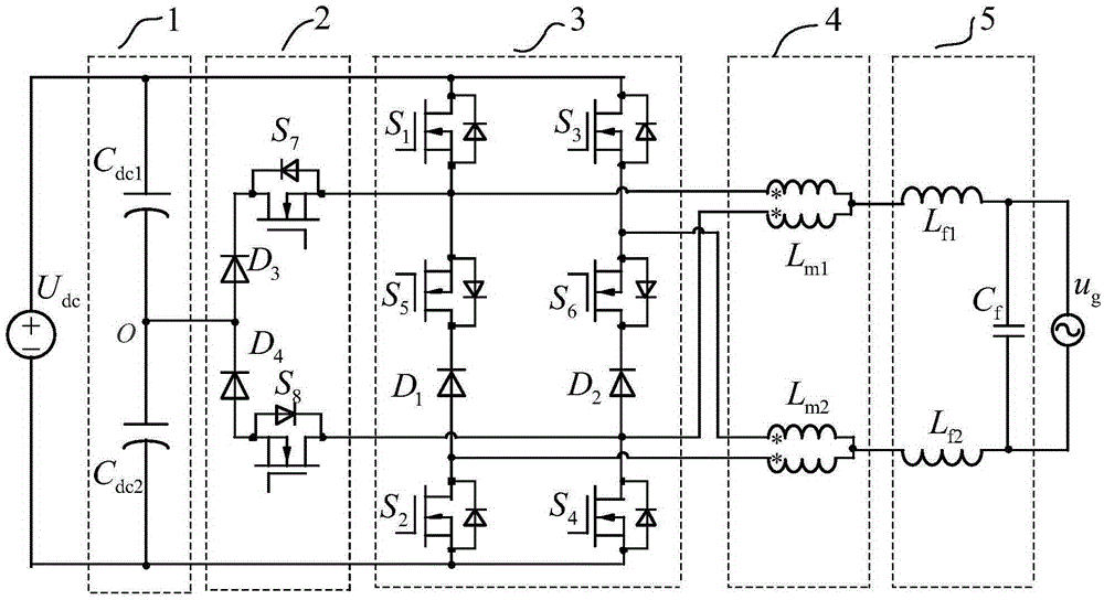
[0075] Such as figure 2 As shown, the common mode inductor branch 4 includes the first common mode filter inductor L m1 and a second common-mode filter inductor L m2 .

[0076] Input DC source U dc The positive output terminals of the first divider capacitor C dc1 positive pole of the first power switch tube S 1 The drain and the third power switch S 3 The drain connection of the input DC source U dc The negative output terminals are respectively connected to the second voltage dividing capacitor C dc2 The negative pole of the second power switch tube S 2 source of the fourth power switch S 4 The source connection; the first voltage divider capacitor C dc1 The negative pole of the second voltage dividing capacitor C dc2 The anode of the third power diode D 3 The anode of the fourth power diode D 4 The cathode connection; the third power diode D 3 The cathode and the seventh power switch S 7 The drain connection of the seventh power switch tube S 7 The sources o...

Embodiment 2

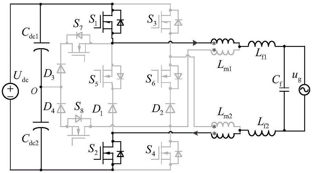
[0090] Such as Figure 5 As shown, the common mode inductance branch 4 includes the common mode filter inductance L m .

[0091] Input DC source U dc The positive output terminals are respectively connected to the first voltage dividing capacitor C dc1 positive pole of the first power switch tube S 1 The drain and the third power switch S 3 The drain connection of the input DC source U dc The negative output terminals are respectively connected to the second voltage dividing capacitor C dc2 The negative pole of the second power switch tube S 2 source of the fourth power switch S 4 The source connection; the first voltage divider capacitor C dc1 The negative pole of the second voltage dividing capacitor C dc2 The anode of the third power diode D 3 The anode of the fourth power diode D 4 The cathode connection; the third power diode D 3 The cathode and the seventh power switch S 7 The drain connection of the seventh power switch tube S 7 The sources of the first po...

Embodiment 3

[0094] Such as Image 6 As shown, the common mode inductance branch 4 includes the common mode filter inductance L m .

[0095] Input DC source U dc The positive output terminals are respectively connected to the first voltage dividing capacitor C dc1 positive pole of the first power switch tube S 1 The drain and the third power switch S 3 The drain connection of the input DC source U dc The negative output terminals are respectively connected to the second voltage dividing capacitor C dc2 The negative pole of the second power switch tube S 2 source of the fourth power switch S 4 The source connection; the first voltage divider capacitor C dc1 The negative pole of the second voltage dividing capacitor C dc2 The anode of the third power diode D 3 The anode of the fourth power diode D 4 The cathode connection; the third power diode D 3 The cathode and the seventh power switch S 7 The drain connection of the seventh power switch tube S 7 The sources of the first pow...


PUM


Abstract

The invention discloses a five-level double-step down grid-connected inverter and belongs to the field of inverters. The structure comprises an input direct current source, an input voltage-dividing capacitor branch, a neutral-point clamped branch, a full bridge power branch, a common mode inductor branch and an output filtering branch, wherein the common mode inductor branch and each power branch comprise multiple configuration and connection modes. The beneficial effects are that power switch tubes and filtering inductors are low in voltage change ratio, the size of a filter is small, and the power density and the conversion efficiency are high; the number of filtering inductors in the output filtering branch is reduced through coupling inductors, thereby achieving a bidirectional power flow; and the inverter is suitable for occasions of middle and high voltage and large power, and has a wide application prospect in the new energy grid-connected power generation field with high requirements for inverter power density and conversion efficiency.

Description

technical field [0001] The invention relates to a five-level double-buck grid-connected inverter, which belongs to the technical field of power electronic converters. Background technique [0002] With the increasingly severe energy crisis and environmental pollution, new energy power generation technologies such as solar energy, wind energy, and fuel cells have become the focus of attention and research around the world. According to whether the new energy power generation system is connected to the public grid, it is divided into two modes: grid-connected operation and independent operation. Among them, grid-connected operation is the most common way for new energy power generation applications, and grid-connected inverters are used as new energy grid-connected systems. It is of great significance to improve its reliability, efficiency and power density. [0003] The dual-buck inverter has the advantages of high reliability and freewheeling of independent diodes, but its ...

Claims


Application Information

Patent Timeline
Patent Type & Authority Applications(China)
IPC IPC(8): H02J3/38H02M7/797
Inventor 张犁赵晋泉
Owner HOHAI UNIV
Why Eureka
Try Eureka