

Wet-type purification treatment method and device for flue gas of domestic garbage incineration power plant
A technology of domestic waste incineration and wet purification, applied in chemical instruments and methods, separation methods, ammonium halide, etc., can solve the problems of high equipment investment and high operating costs, and achieve the effects of high dust removal efficiency, high maintenance costs and stable operation.
- Summary
- Abstract
- Description
- Claims
- Application Information
AI Technical Summary
Problems solved by technology
Method used
Image

Examples
Embodiment 1
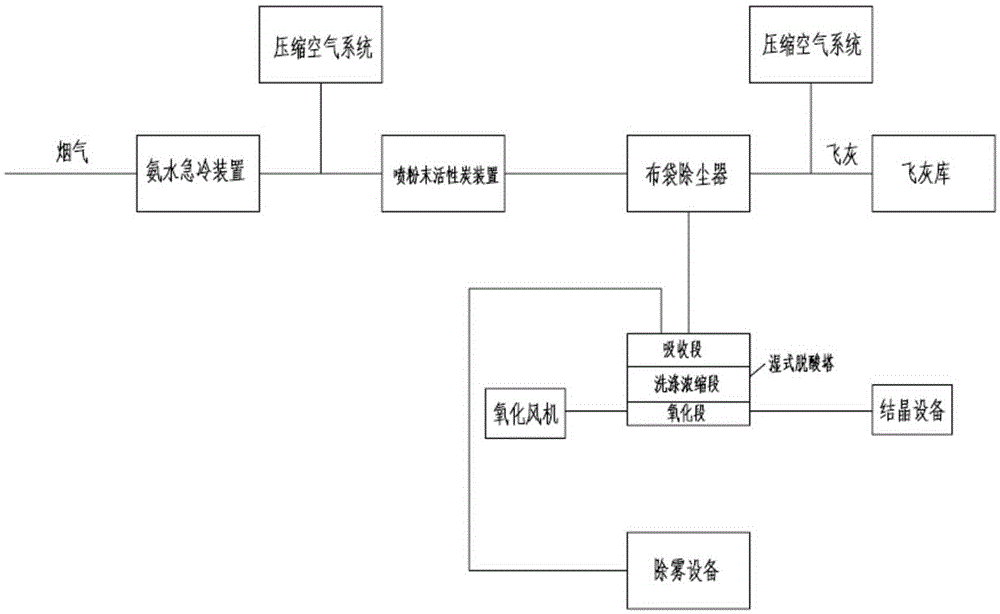
[0043] Such as figure 1 As shown, the flue gas wet purification treatment device of the domestic waste incineration power plant in this embodiment includes an ammonia water quenching device, a powder activated carbon spraying device, a bag filter, a wet deacidification tower and a demisting device. The ammonia water quenching device, spraying The powdered activated carbon device and the bag filter are connected through the ventilation pipe, the gas inlet end of the ammonia water quenching device can be connected with the flue gas outlet of the domestic waste incineration power plant, and the ventilation pipe between the ammonia water quenching device and the powder activated carbon spraying device is also connected. Compressed air system, a compressed air system is installed under the ash hopper of the bag filter. The ash hopper is connected to the fly ash storage through pipelines, and the outlet flue of the bag filter is connected to the washing and concentrating section of t...
PUM
 Abstract
Description
Claims
Application Information